Floor system formed by cold bending type steel combination beam

A technology of cold-formed steel and composite beams, applied in the direction of floor slabs, building components, building structures, etc., can solve the problems of large proportion of shear connectors, reducing the actual use height of floors, and small operating space, saving engineering construction. Time and labor costs, increased floor operation space, and fast on-site construction

Active Publication Date: 2017-06-27
SHANGHAI OPEN STEEL JOIST
View PDF10 Cites 0 Cited by
  • Summary
  • Abstract
  • Description
  • Claims
  • Application Information

AI Technical Summary

Problems solved by technology

The common disadvantage of these two combination methods is that the fixing and combination of shear connectors, whether it is stud connection, bending bar connection or channel steel connection, shear connectors account for a large proportion of the structure, and the material consumption is relatively large; Yes, the workload of welding and installation of on-site shear connectors is huge, which requires a lot of labor and time; although the truss-concrete composite structure uses a small amount of steel, the welding workload is large and the production efficiency is low; the on-site construction is troublesome, which in turn affects the project Construction Schedule
[0003] In addition, in the traditional H-shaped steel composite structure, the bottom surface is usually pre-laid with a laminated steel plate as the bottom formwork, which cannot be disassembled, and the economic benefits are not good; the concrete reinforcement on the floor usually adopts double-layer two-way reinforcement, and the steel content is high; pipelines and Other structures that need to be fixed under the floor can only be fixed and crossed at the bottom of the steel beam, thus greatly reducing the actual use height of the floor; and the operation space is small, the construction is inconvenient, the labor intensity is high, and the cost is high

Method used


Image

  • Floor system formed by cold bending type steel combination beam
  • Floor system formed by cold bending type steel combination beam
  • Floor system formed by cold bending type steel combination beam

Examples


Embodiment Construction

[0015] The present invention will be described in further detail below in conjunction with the embodiments in the accompanying drawings, but this does not constitute any limitation to the present invention.

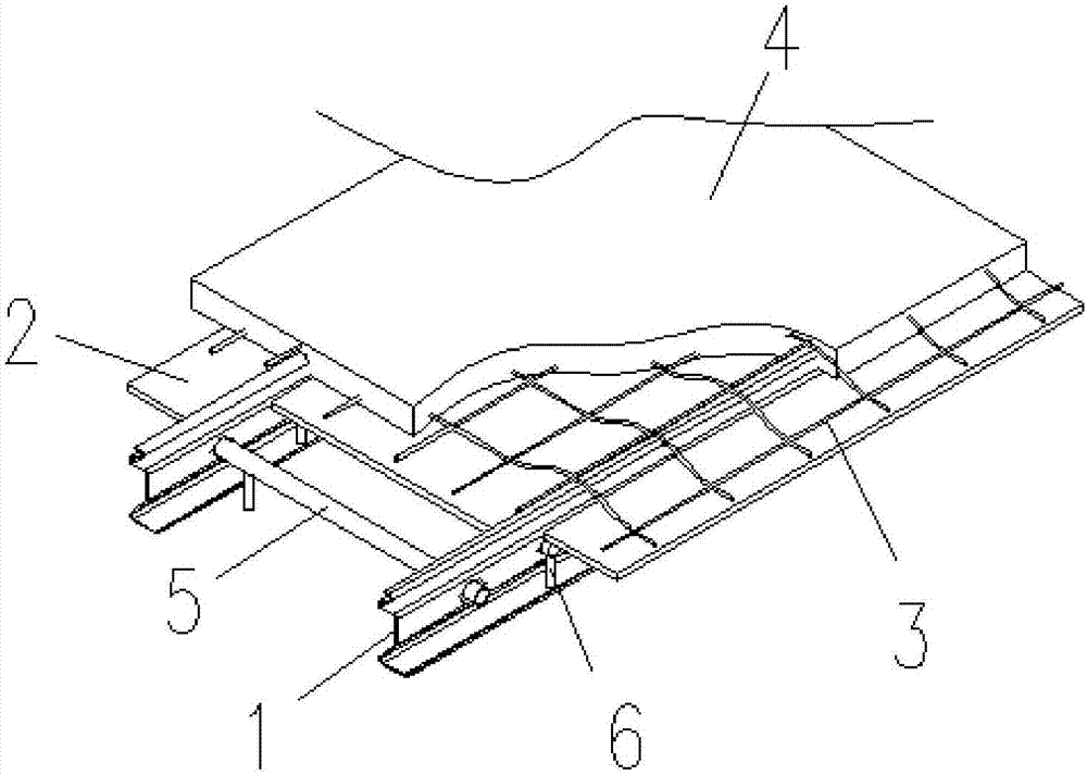
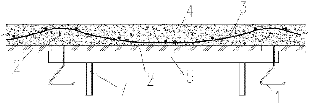
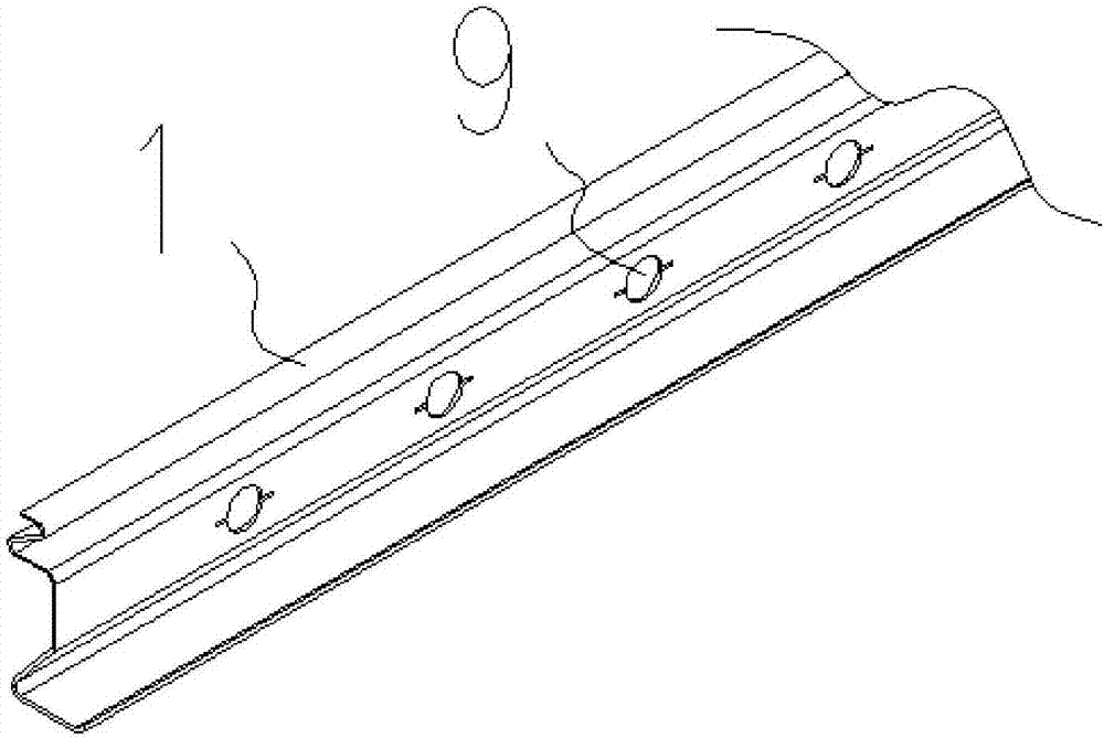
[0016] Such as Figure 1 to Figure 3 As shown, a floor system composed of cold-formed steel composite beams includes cold-formed steel 1, floor template 2 and floor concrete layer 4; two cold-formed steels 1 are arranged in parallel, and the The inner side of the room is provided with a long supporting rod 5, and the outer side is provided with a short supporting rod 6, forming a group of cold-formed steel; Fixed; the floor concrete layer 4 is provided with a floor reinforcement mesh 3, and the floor reinforcement mesh 3 is arranged in an arc-shaped structure, located on a group of cold-formed steel; the cross-section of the cold-formed steel 1 is a multi-curved surface structure, and a plurality of sets of connecting holes 9 are arranged along the length direction; the ...


PUM


Abstract

The invention provides a floor system formed by cold bending type steel combination beam, comprising cold bending type profile steels, a floor template and a floor concrete layer; two cold bending type profile steels are arranged in parallel, and the inside between the cold bending type profile steels is provided with a long holding rod, and the outside is provided with a short holding rod, thus a group of cold bending type profile steels is formed; the upsides of the cold bending type profile steels are crossed trough the floor template and fixed with the floor concrete layer on the floor template; a floor reinforcement mesh piece is arranged in the floor concrete layer and the floor concrete layer is located above a group of cold bending type profile steels; the cross section of each cold bending type profile steel is multi-curve structure, and the cold bending type profile steels are provided with multiple groups of connecting holes along the length direction; the long holding rod crosses through the connecting holes and is arranged at both ends of a group of cold bending type profile steels, and the short holding rod is arranged on the connecting holes at the inner parts of the cold bending type profile steels. The floor system adopts the cold bending type profile steels and combines with the long and short holding rods and the floor reinforcement mesh pieces; the steel content of the floor is greatly reduced; the component processing is simple, the site construction speed is fast, a lot of construction times are saved, and the cost is reduced.

Description

technical field [0001] The invention belongs to the technical field of construction and civil engineering, and in particular relates to a floor system composed of cold-formed steel composite beams. Background technique [0002] The steel-concrete composite structure combines the advantages of steel and concrete. Using concrete in the compression zone can better utilize the material characteristics of steel and concrete, avoid their respective weak surfaces, and give full play to the strength of the material. potential. For traditional steel-concrete composite structures, the usual practice is to combine H-shaped steel or trusses with concrete slabs. The common disadvantage of these two combination methods is that the fixing and combination of shear connectors, whether it is stud connection, bending bar connection or channel steel connection, shear connectors account for a large proportion of the structure, and the material consumption is relatively large; Yes, the workload...

Claims


Application Information

Patent Timeline
Patent Type & Authority Applications(China)
IPC IPC(8): E04B5/17
CPCE04B5/17Y02B30/00
Inventor 陈明
Owner SHANGHAI OPEN STEEL JOIST
Why Eureka
Try Eureka