
Monitoring device and method for hydrate deposition law in deepwater gas well testing period

A monitoring device and hydrate technology, which are applied in the directions of surveying, earth-moving drilling and production, wellbore/well components, etc., can solve the problem of different thicknesses of hydrate layers and cannot effectively measure the deposition thickness of hydrate layers. The hydrate deposition law, thickness and law Issues such as insufficient research

Active Publication Date: 2017-06-27
CHINA UNIV OF PETROLEUM (EAST CHINA)
View PDF9 Cites 11 Cited by
  • Summary
  • Abstract
  • Description
  • Claims
  • Application Information

AI Technical Summary

Problems solved by technology

[0005] Among the few devices related to hydrate deposition in vertical pipelines, most of them observe and study the deposition process through visual windows, and cannot effectively measure the deposition thickness of the hydrate layer and the deposition law of hydrate under different working conditions, that is, the hydrate formation section or form a hydrate layer but the intermediate fluid can flow, or the thickness of the hydrate layer in different segments is different
[0006] To sum up, in the process of deep-water gas well testing, the research on the location, thickness and regularity of hydrate deposition is still insufficient. Based on the study of the influence of temperature and pressure, water content, pipe wall polarity and other factors on hydrate deposition

Method used


Image

  • Monitoring device and method for hydrate deposition law in deepwater gas well testing period
  • Monitoring device and method for hydrate deposition law in deepwater gas well testing period
  • Monitoring device and method for hydrate deposition law in deepwater gas well testing period

Examples


Embodiment Construction

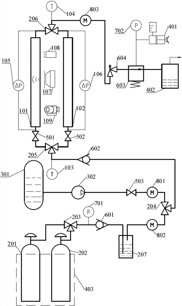
[0021] figure 1 As shown in Fig. 1, the monitoring device for the regularity of hydrate deposition during deep-water gas well testing includes: gas-liquid delivery system, hydrate monitoring system, and auxiliary system; the gas-liquid delivery system provides gas source and liquid source, which are mixed and delivered to the hydrate monitoring system; The hydrate monitoring system forms hydrates in the simulated wellbore under high pressure and low temperature conditions, records and observes the process of hydrate crystallization, deposition and clogging; the auxiliary system performs gas post-processing and realizes the safety control of the device.

[0022] Gas-liquid delivery system, including: cooling water bath 403, first gas cylinder 201, second gas cylinder 202, first three-way valve 203, first pressure sensor 701, first one-way valve 601, first container 207, water storage Tank 301, booster pump 302, third stop valve 503, first mass flow meter 801, second mass flow m...


PUM


Abstract

The invention relates to a monitoring device for a hydrate deposition law in a deepwater gas well testing period. The monitoring device for the hydrate deposition law in the deepwater gas well testing period comprises a gas-liquid conveying system, a hydrate monitoring system and an auxiliary system. The gas-liquid conveying system supplies a gas source and a liquid source. Gas and liquid are mixed to be conveyed to the hydrate monitoring system. According to the hydrate monitoring system, a hydrate is formed in a simulation wellbore under the condition of high pressure and low temperature, and the crystallizing and depositing-blocking process of the hydrate is recorded and observed. The auxiliary system conducts post-processing on gas and safely controls the device. The generating process of the hydrate can be simulated as a dynamic process which conforms to the actual testing process, and the process from depositing, adhering to blocking of the hydrate can be observed in real time; and the depositing distribution situation of three phases of gas-water-hydrate in different positions can be observed in an imaging mode in real time through ultrasonic imaging, the distribution law of the thickness of a hydrate layer in the axial direction of the wellbore is obtained, and important significance for solving the problem of flow guarantee of deepwater testing is achieved.

Description

technical field [0001] The invention belongs to the field of flow assurance in the testing process of deep-water gas wells, and in particular relates to a monitoring device and method for hydrate deposition rules during testing of deep-water gas wells, which are used for simulating initial well opening, variable flow rate exploitation, well shut-in and other testing stages. The law of hydrate deposition and blockage provides a basis for flow guarantee. Background technique [0002] With the depletion of onshore oil resources and the continuous exploitation of offshore oil, the exploitation of deep water oil and gas resources has increasingly become a hot field of oil development. In the deep water field, the environment of low temperature and high pressure can easily promote the formation of hydrates. The hydrates solidify on the pipe wall to cause throttling effect, accelerate the deposition process, and form a vicious circle, which will lead to wellbore blockage and cause ...

Claims


Application Information

Patent Timeline
IPC IPC(8): E21B47/001E21B47/002E21B47/10
CPCE21B47/10E21B41/0099E21B47/001E21B47/002
Inventor 高永海崔燕春孙宝江陈野李昊赵欣欣
Owner CHINA UNIV OF PETROLEUM (EAST CHINA)
Learn More