Fast charge and discharge type power battery safety cap

A power battery and fast-discharging technology, which is applied in the direction of battery box/jacket, battery pack components, circuits, etc., can solve the problems of explosion-proof membranes that are easy to deform and rupture, easy to burn, and battery explosion, so as to improve safety explosion-proof performance and meet Fast charging and fast discharging, the effect of eliminating gaps

Inactive Publication Date: 2017-06-27
朱剑
View PDF2 Cites 0 Cited by
  • Summary
  • Abstract
  • Description
  • Claims
  • Application Information

AI Technical Summary

Problems solved by technology

[0005] In order to solve the problem that the explosion-proof film of the power battery cap in the prior art cannot be normally opened to release the pressure after being turned over, the internal resistance of the cap is unstable, the instantaneous high current cannot be passed smoothly to meet fast charging, the high current generates heat, the battery is easy to burn, and the service life is short, and When the cap is produced normally and the cap is packaged with the steel shell, the explosion-proof film of the cap is easily deformed and broken, the misalignment and fracture of the explosion-proof film and the orifice plate lead to the scrapping of the battery, and the overlapping deformation of the explosion-proof film causes the battery to explode and be easy to burn. The purpose of the present invention is to provide a After the explosion-proof membrane is flipped over, it will normally open and release pressure, with stable internal resistance, long service life, no deformation and misalignment, stable explosion-proof performance, safe production and use of fast-charging and fast-discharging power battery safety caps

Method used


Image

  • Fast charge and discharge type power battery safety cap
  • Fast charge and discharge type power battery safety cap
  • Fast charge and discharge type power battery safety cap

Examples


Embodiment Construction

[0025] The present invention will be further described below with reference to the accompanying drawings and embodiments.

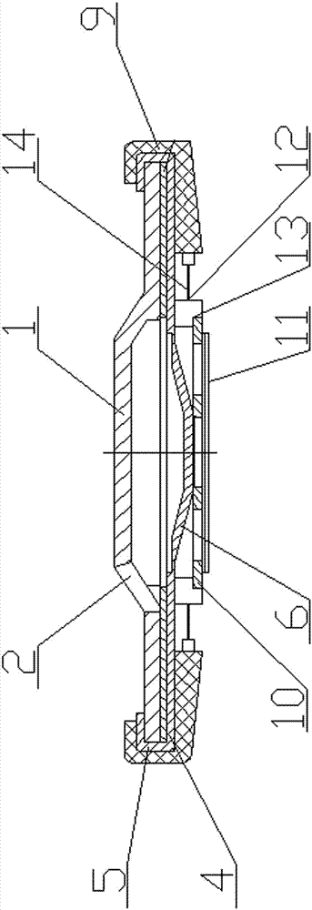
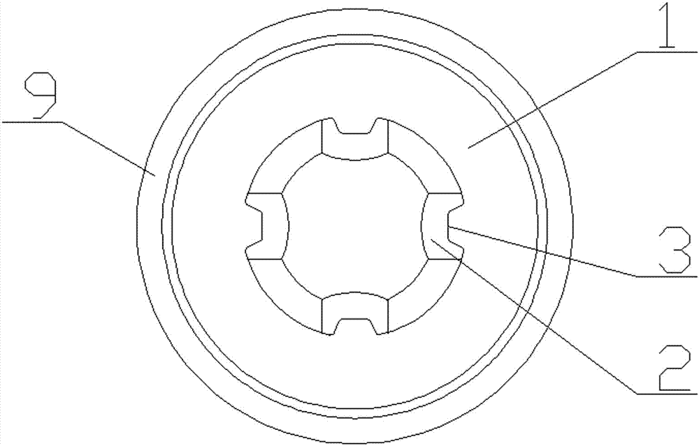
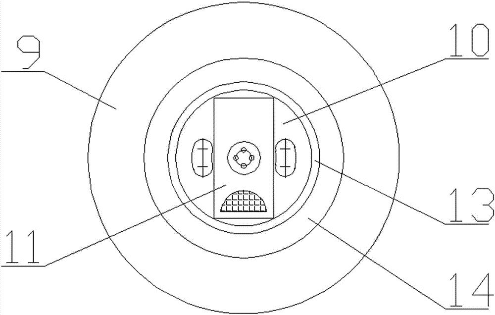
[0026] Figure 1-5 Shown: a fast-charging and fast-discharging power battery safety cap includes an upper cap 1, an explosion-proof membrane 4 with a wall 5, an orifice plate 10, a transition tab 11, an inner sealing ring 12 and an outer sealing ring 9, the upper cap 1 It is arranged on the upper end surface of the explosion-proof membrane 4 in a state of being bent and pressed inward by the wall body 5 and ultrasonically welded on the upper end surface of the upper cap 1 at multiple points. The upper cap 1 is evenly distributed with a plurality of air holes 2, and each air hole 2 There is an overturned pre-stressed pressure relief buckle 3 connected to the upper cap 1, the center of the lower end face of the explosion-proof membrane 4 is convex in the shape of a steamed bun-loading bulge structure 6, and the steamed bun-loading bulge structure 6 is a pla...


PUM


Abstract

The invention relates to a fast charge and discharge type power battery cap which comprises an upper cap, an explosion-proof film with walls, a pore plate, an inner sealing ring and an outer sealing ring. The upper cap is arranged on the upper end surface of the explosion-proof film in such a state that the upper cap is compressed by the walls in an inwardly bent manner and the walls are arranged on the upper surface of the upper cap by means of ultrasonic multipoint welding, a plurality of air outlet holes are uniformly formed in the upper cap, the pore plate is welded in the center of the lower end surface of the explosion-proof film, the outer sealing ring wraps the outer wall of the upper cap and the outer wall of the explosion-proof film by means of gluing, the upper edge and the lower edge of the outer sealing ring are inwardly bent to glue and compress the upper cap or the upper ends surfaces of the bent walls of the explosion-proof film and the lower end surface of the explosion-proof film, and two arc-shaped pressure relief carved grooves which are formed in the same circumference, are not connected with each other and are symmetrically formed are formed in the periphery of the center, which is welded with the pore plate, of the explosion-proof film.

Description

technical field [0001] The invention relates to a battery cap, in particular to a fast-charging and fast-discharging type power battery safety cap. Background technique [0002] The power battery cap is a key component of the power battery, also known as the high-current lithium-ion battery. It is directly related to the battery's safety performance, capacity, service life, safe passage of high current, and the production and use safety of producers and users. The existing cylindrical power battery cap is mainly composed of an upper cap, a gasket, an explosion-proof membrane with a wall, a sealing ring, and an orifice plate. When such a cap is charged and discharged at a high rate of battery activation or when the battery is abnormal, the gasket heats up seriously, and the ability of the explosion-proof membrane to seal the annular pressure relief ring to pass the current through the current cross-sectional area is severely limited. The battery is abnormally hot when the cu...

Claims


Application Information

Patent Timeline
Patent Type & Authority Applications(China)
IPC IPC(8): H01M2/12H01M2/04H01M2/08H01M50/147H01M50/186H01M50/342
CPCH01M50/152H01M50/183H01M50/383H01M50/3425Y02E60/10
Inventor 朱剑
Owner 朱剑
Why Eureka
Try Eureka