Explosion-proof and combustion-proof cap for power battery

A power battery and cap technology, which is applied in the field of explosion-proof and combustion-proof caps for cylindrical lithium-ion power batteries, can solve the problems of easy combustion of batteries, easy deformation and rupture of explosion-proof membranes, and short service life, so as to achieve no explosion and combustion hazards and improve safety Explosion-proof performance, the effect of reducing the overall internal resistance

Active Publication Date: 2017-12-01
泰兴市新业电子有限公司
View PDF1 Cites 0 Cited by
  • Summary
  • Abstract
  • Description
  • Claims
  • Application Information

AI Technical Summary

Problems solved by technology

[0005] In order to solve the problem that the explosion-proof membrane of the power battery cap in the prior art cannot be normally opened to release the pressure, the internal resistance of the cap is unstable, the instantaneous high current cannot pass smoothly, the use of large current generates serious heat, the battery is easy to burn, the service life is short, and the normal production of the cap And when the cap is packaged with the steel shell, the explosion-proof membrane of the cap is easily deformed and broken, the dislocation and fracture of the explosion-proof membrane and the orifice plate cause the battery to be scrapped, and the superimposed deformation of the explosion-proof membrane causes the battery to explode and be easy to burn. The purpose of the present invention is to provide an explosion-proof membrane After turning over, it will normally open for pressure relief, stable internal resistance, long service life, no deformation and misalignment, stable explosion-proof performance, safe production and use of power battery explosion-proof and combustion-proof caps

Method used


Image

  • Explosion-proof and combustion-proof cap for power battery
  • Explosion-proof and combustion-proof cap for power battery
  • Explosion-proof and combustion-proof cap for power battery

Examples


Embodiment Construction

[0026] The present invention will be further described below in conjunction with the drawings and embodiments.

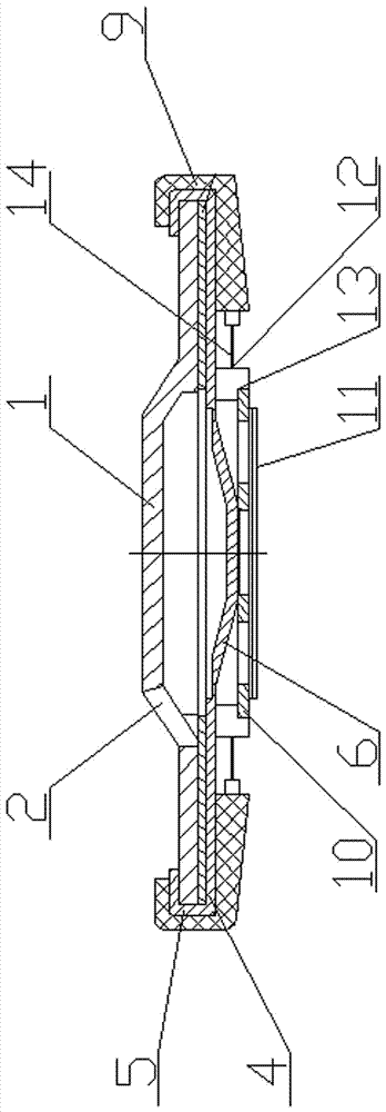
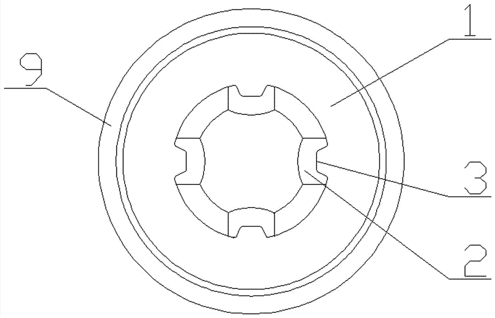
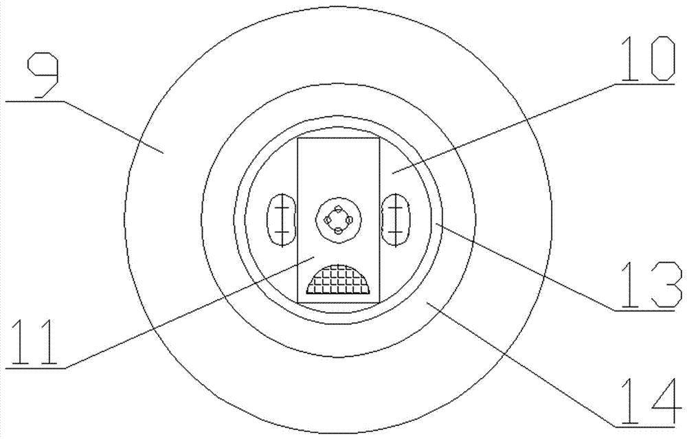
[0027] Figure 1-4 Shown: A power battery explosion-proof and anti-combustion cap includes an upper cap 1, an explosion-proof membrane 4 with a wall 5, an orifice plate 10, a transition tab 11, an inner sealing ring 12 and an outer sealing ring 9. The upper cap 1 is set on the explosion-proof The upper end surface of the membrane 4 is in the state of being bent and pressed inward by the wall 5 and ultrasonically welded to the upper end surface of the upper cap 1 by multi-point ultrasonic welding. The upper cap 1 is evenly distributed with multiple air holes 2 and each air hole 2 is provided with a connection The overturned pre-stress relief buckle 3 on the upper cap 1 and the center of the lower end surface of the explosion-proof membrane 4 protrude downward into a steamed bun-shaped raised structure 6. The steamed bun-shaped raised structure 6 is platform-shaped and m...


PUM

PropertyMeasurementUnit
internal resistanceaaaaaaaaaa

Abstract

The invention relates to an explosion-proof and combustion-proof cap for a power battery, which includes an upper cap, an explosion-proof membrane with a wall, an orifice plate, and inner and outer sealing rings. Tight and ultrasonic multi-point welded on the upper end of the upper cap, there are multiple air holes evenly distributed on the upper cap, each air hole is equipped with a flip prestressed pressure relief button connected to the upper cap, and the lower end of the explosion-proof membrane is welded with an orifice , the outer sealing ring is coated with glue to wrap the outer wall of the upper cap and the outer wall of the explosion-proof membrane, and the upper and lower sides of the outer sealing ring are bent inward and coated with glue to press the upper end surface of the bent wall of the upper cap or the explosion-proof membrane and the lower end surface of the explosion-proof membrane, It is characterized in that: the explosion-proof membrane is evenly distributed with a plurality of pressure relief lines respectively corresponding to a plurality of flipped prestressed pressure relief buckles, the pressure relief line is a single arc curve that is not closed, or the pressure relief line is two A structure in which the lines above the root intersect at a point.

Description

Technical field [0001] The invention relates to a battery cap, in particular to an explosion-proof and anti-combustion cap for a cylindrical lithium ion power battery with micro-resistance, no explosion, no combustion, and large current. Background technique [0002] The power battery cap is a key component of the power battery, also known as the high-current lithium-ion battery. It is directly related to the battery's safety performance, capacity, service life, safety through high current, production and use safety of producers and users. The existing cylindrical power battery cap is mainly composed of an upper cap, a gasket, an explosion-proof membrane with a wall, a sealing ring, and an orifice plate. When such a cap is activated by high-rate charging and discharging of the battery or when the battery is abnormal, the gasket heats up severely, and the ability of the explosion-proof membrane to seal the annular pressure relief ring to pass the current cross-sectional area curre...

Claims


Application Information

Patent Timeline
Patent Type & Authority Patents(China)
IPC IPC(8): H01M2/04H01M2/08H01M2/12H01M50/143H01M50/147H01M50/19H01M50/342
CPCH01M50/147H01M50/183H01M50/30Y02E60/10
Inventor 朱鑫宇朱剑
Owner 泰兴市新业电子有限公司
Why Eureka
Try Eureka