Quick-charging battery safety cap

A rechargeable battery and cap technology, which is applied in the field of fast-charge battery safety caps, can solve the problems of explosion-proof membranes that are easily deformed and broken, easy to burn, and battery explosions, and achieve the effects of improving safety and explosion-proof performance, satisfying fast charging and fast discharging, and eliminating gaps

Inactive Publication Date: 2020-05-12
史红桂
View PDF1 Cites 1 Cited by
  • Summary
  • Abstract
  • Description
  • Claims
  • Application Information

AI Technical Summary

Problems solved by technology

[0005] In order to solve the problem that the explosion-proof film of the power battery cap in the prior art cannot be normally opened to release the pressure after being turned over, the internal resistance of the cap is unstable, the instantaneous high current cannot be passed smoothly to meet fast charging, the high current generates heat, the battery is easy to burn, and the service life is short, and When the cap is produced normally and the cap is packaged with the steel shell, the explosion-proof film of the cap is easily deformed and broken, the misalignment and fracture of the explosion-proof film and the orifice plate lead to the scrapping of the battery, and the overlapping deformation of the explosion-proof film causes the battery to explode and be easy to burn. The purpose of the present invention is to provide a After the explosion-proof membrane is flipped over, it will normally open and release pressure, with stable internal resistance, long service life, no deformation and misalignment, stable explosion-proof performance, safe production and use of fast-charging and fast-discharging power battery safety caps

Method used


Image

  • Quick-charging battery safety cap
  • Quick-charging battery safety cap
  • Quick-charging battery safety cap

Examples


Embodiment Construction

[0025] The present invention will be further described below in conjunction with drawings and embodiments.

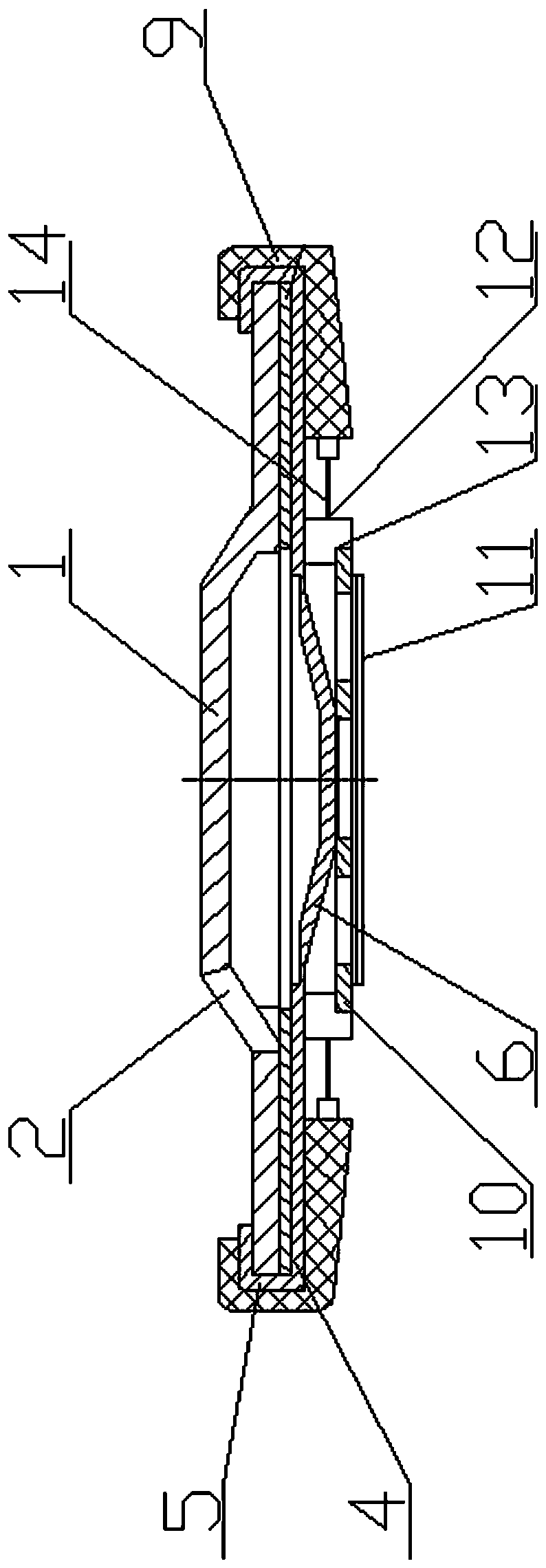
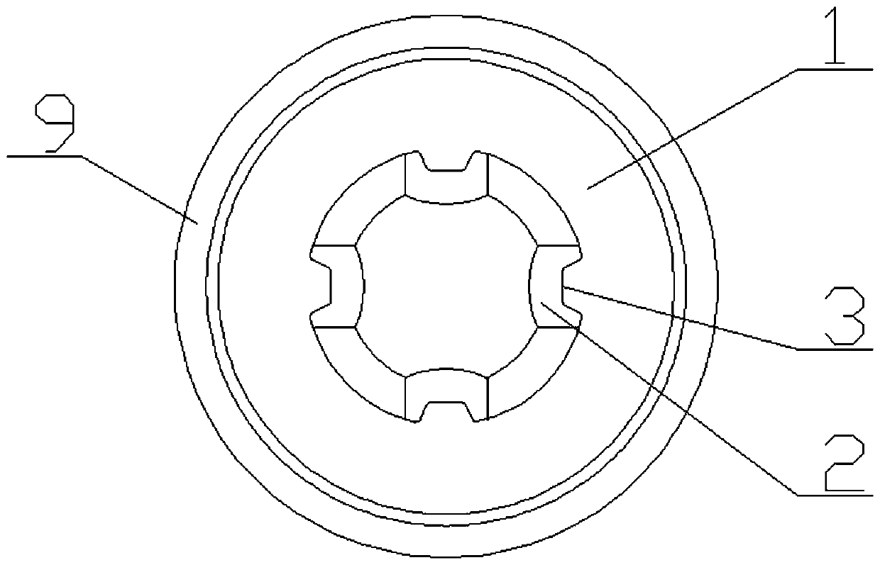
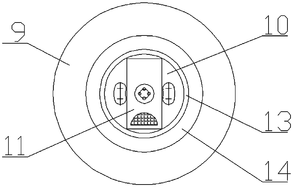
[0026] Figure 1-5 As shown: a fast charging battery safety cap includes an upper cap 1, an explosion-proof membrane 4 with a wall 5, an orifice plate 10, a transition tab 11, an inner sealing ring 12 and an outer sealing ring 9, and the upper cap 1 is arranged on the explosion-proof membrane 4. The upper end face is in a state of being bent and pressed inward by the wall body 5 and ultrasonically multi-point welded on the upper end face of the upper cap 1. The upper cap 1 is evenly distributed with a plurality of air holes 2, and each air hole 2 is equipped with a connection The reverse prestressed pressure relief button 3 on the upper cap 1, the center of the lower end surface of the explosion-proof membrane 4 protrudes downwards to form a raised structure 6 for the steamed buns, the raised structure 6 for the steamed buns is platform-shaped and multi-point laser spot...


PUM


Abstract

The invention relates to a quick-charging battery safety cap, which comprises an upper cover cap, an explosion-proof membrane with a wall body, a pore plate, an inner sealing ring and an outer sealingring, wherein the upper cover cap is arranged on the upper end face of the explosion-proof membrane, the wall body is bent and pressed inwards, and is welded to the upper end face of the upper covercap in an ultrasonic wave multi-point welding mode, a plurality of gas outlet holes are uniformly distributed in the upper cover cap, the pore plate is welded in the center of the lower end surface ofthe explosion-proof membrane, the outer wall of the upper cover cap and the outer wall of the explosion-proof membrane are coated with the outer sealing ring in a gluing manner, the upper edge and the lower edge of the outer sealing ring are bent inwards to press the upper end face of the upper cover cap or the bent wall body of the explosion-proof membrane and the lower end face of the explosion-proof membrane in a gluing manner, and two arc-shaped pressure relief grooves which are located on the same circumference, not connected and symmetrically formed are formed in the periphery of the center of the pore plate welded on the explosion-proof membrane.

Description

technical field [0001] The invention relates to a battery cap, in particular to a fast-charging battery safety cap. Background technique [0002] The power battery cap is a key component of the power battery, also known as a high-current lithium-ion battery. It is directly related to the battery's safety performance, capacity, service life, safe passage of high current, production and use safety of producers and users. The existing cylindrical power battery cap mainly consists of an upper cap, a gasket, an explosion-proof membrane with a wall, a sealing ring, and an orifice plate. When such a cap is charged and discharged at a high rate of battery activation or when the battery is abnormal, the gasket will heat up severely, and the ability of the explosion-proof membrane to seal the circular pressure relief ring to pass the current cross-sectional area is severely limited. The battery is abnormally hot when the current is flowing, and the power is cut off or turned on in ad...

Claims


Application Information

Patent Timeline
Patent Type & Authority Applications(China)
IPC IPC(8): H01M2/04H01M2/08H01M2/12H01M50/152H01M50/188
CPCH01M2200/20H01M50/152H01M50/183H01M50/383H01M50/3425Y02E60/10
Inventor 史红桂
Owner 史红桂
Why Eureka
Try Eureka