
Carbon dioxide laser tube with new structure and vacuum flange modules

A vacuum flange, carbon dioxide technology, applied in lasers, laser parts, laser parts and other directions, can solve the problems of difficult to guarantee the quality of carbon dioxide laser tubes, unable to place the lens protective cover, difficult to ensure the consistency of accuracy, etc. Dependence on the grinding accuracy of the nozzle, good sealing effect, easy installation and operation

Pending Publication Date: 2017-06-27
北京镭海激光科技有限公司
View PDF5 Cites 1 Cited by
  • Summary
  • Abstract
  • Description
  • Claims
  • Application Information

AI Technical Summary

Problems solved by technology

The total reflection mirror and output reflection mirror of this type of carbon dioxide laser tube are directly bonded to the nozzle with glue. After bonding, the lens is difficult to adjust, and the lens protection cover cannot be placed. Due to technological reasons, it is difficult to guarantee its accuracy. consistency
The tungsten rod electrodes installed at both ends of the tube body are small and sharp, so they are easy to damage and cause partial rupture of the laser tube or air leakage, which makes it difficult to guarantee the quality of this type of carbon dioxide laser tube.

Method used


Image

  • Carbon dioxide laser tube with new structure and vacuum flange modules
  • Carbon dioxide laser tube with new structure and vacuum flange modules

Examples


Embodiment Construction

[0012] The present invention will be described in detail below in conjunction with the accompanying drawings.

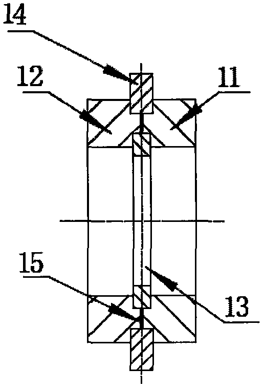
[0013] Such as Figure 1 to Figure 2 As shown, a carbon dioxide laser tube with a vacuum flange assembly of a new structure includes a tube body and a lens, and also includes two vacuum flange assemblies 7, and the two vacuum flange assemblies 7 are glued to the nozzles at both ends of the tube body. Then, the lens is installed on the vacuum flange assembly 7 connected to the nozzle, and the lens is a total reflection mirror 8 or an output reflection mirror 16; the glass part of the carbon dioxide laser tube is composed of a gas storage tube 1, a gas return tube 2, a water cooling tube 3, and a discharge tube 4 and water nozzle 5, the pipe body is a three-layer casing structure, the innermost layer is the discharge tube 4, the middle is the water-cooled tube 3, the outermost layer is the gas storage tube 1, and the gas return tube 2 is used to connect the discharge t...


PUM


Abstract

The present invention discloses a carbon dioxide laser tube with a new structure and vacuum flange modules. The carbon dioxide laser tube comprises a tube body, a lens and two vacuum flange modules, the two vacuum flange modules are bonded with the tube mouths of two ends of the tube body, the lens is installed on vacuum flange modules connected with a tube mouths, the tube body is a three-layer annular tube structure, the innermost layer of the tube body is a discharge tube, the middle layer of the tube body is a water cooling tube, the outermost layer of the tube body is a gas storage tube, a steam return is configured to communicate the discharge tube with the gas storage tube, the tube mouth at one end having the steam return is provided with a total-reflection mirror, an anode electrode is arranged at the discharge tube of one end provided with the total-reflection mirror, and an output reflector is arranged at the tube mouth of the other end, and a cathode electrode is arranged at the discharge tube of one end provided with the output reflector. The carbon dioxide laser tube with the new structure and vacuum flange modules effectively improves the vacuum seal requirement of the laser tube, reduces the occurrence of the conditions of gas leakage at the bonding positions of the lens and laser tube mouths, improves the quality and the stability of the carbon dioxide laser tube and prolongs the service life.

Description

technical field [0001] The invention belongs to the technical field of carbon dioxide laser tubes, and in particular relates to a carbon dioxide laser tube with a new structure and a vacuum flange assembly. Background technique [0002] The body of the sealed-off carbon dioxide laser tube in the current prior art is made of glass frit and usually has a three-layer casing structure. The central layer is a discharge tube, the middle layer is a water-cooled tube, the outermost layer is a gas storage tube and the The spiral gas return pipe connected by the discharge tube is provided with a total reflection mirror on the nozzle at one end of the gas return pipe, an anode electrode is provided at the discharge tube at this end, and an output reflector is provided at the nozzle at the other end, and the discharge tube at this end Cathode electrodes are set at the center of the laser tube; the electrodes at both ends of the laser tube are tungsten rod electrodes, which are implanted...

Claims


Application Information

Patent Timeline
IPC IPC(8): H01S3/03H01S3/22
CPCH01S3/03H01S3/2232
Inventor 赵立泉张利昌
Owner 北京镭海激光科技有限公司
Learn More