Coil assembly and wireless power transmission system

A technology of wireless energy transfer and coil set, applied in the direction of coil, transformer/inductor coil/winding/connection, transformer, etc., can solve the problems of uneven magnetic field intensity and reduced efficiency of wireless energy transfer system, and achieve the effect of increasing efficiency

Inactive Publication Date: 2017-06-27
IND TECH RES INST
View PDF6 Cites 2 Cited by
  • Summary
  • Abstract
  • Description
  • Claims
  • Application Information

AI Technical Summary

Problems solved by technology

[0003] However, the traditional coil group is composed of two coils with a circular coil pattern, and since the change of the magnetic field strength is inversely proportional to the square of the sensing distance, the traditional circular coil pattern may be prone to magnetic field strength in the area surrounded by the coils. Uneven situation
For example, since the magnetic field at the center of the coil is weaker, the magnetic field closer to the coil is stronger, reducing the efficiency of the wireless energy transfer system

Method used


Image

  • Coil assembly and wireless power transmission system
  • Coil assembly and wireless power transmission system
  • Coil assembly and wireless power transmission system

Examples


Embodiment Construction

[0038] Hereinafter, several examples are presented to illustrate the present invention, but the present invention is not limited to the illustrated examples. Appropriate combinations are also allowed between the embodiments. The words "coupled" and "coupled" used throughout the specification (including claims) of this application may refer to any direct or indirect means of connection. For example, if it is described that the first coil is coupled to the driving device, it should be interpreted that the first device can be directly connected to the driving device, or the first device can be indirectly connected through other devices or some kind of connection means. Connect to the drive unit. Additionally, the term "energy" may refer to at least one current, voltage, charge, electrical energy, or any other electromagnetic wave or waves.

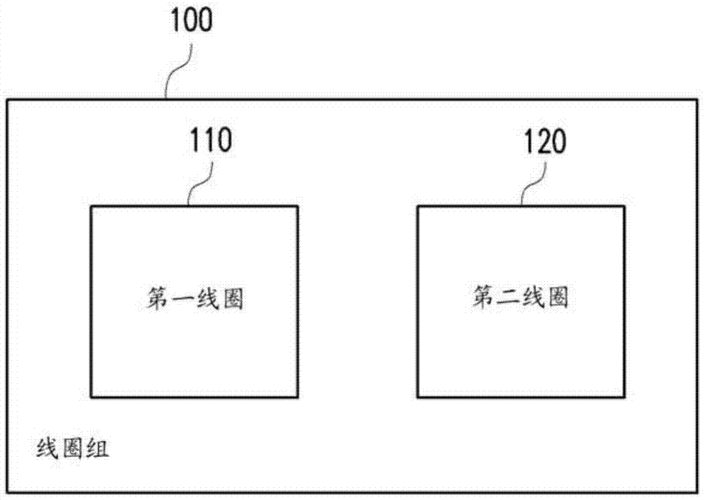
[0039] figure 1 It is a circuit diagram of a coil group drawn according to an embodiment of the present invention. The coil set 100 incl...


PUM


Abstract

A coil assembly and a wireless power transmission system are provided. The coil assembly includes a first coil and a second coil. The first coil is disposed on a first plane. The second coil is disposed on a second plane. The second coil is coupled to the first coil. The second coil includes a plurality of bending section, and the bending sections are connected by a plurality of connection lines to form a single loop.

Description

technical field [0001] The invention relates to a coil group and a wireless energy transmission system. Background technique [0002] In recent years, electronic products using wireless energy transfer have become more and more diversified. The time-varying magnetic field between the coil groups is used to exchange energy. The time-varying magnetic field is generated by the current on the coil. Therefore, how to improve the performance of electromagnetic induction Efficiency is an important topic at present. Generally speaking, a magnetic resonance wireless energy transmission system may include four independent coils, two of which form a transmitting coil group (Transmitter), which can be used as a driving coil and a transmitting coil respectively; Two independent coils form a receiving coil group (Receiver), which are respectively used as a receiving coil and a load coil. The drive coil generates an induced electro-magnetic force (emf) on the transmission coil through in...

Claims


Application Information

Patent Timeline
Patent Type & Authority Applications(China)
IPC IPC(8): H02J50/12H01F27/28H01F27/30H01F38/14
CPCH01F27/28H01F27/306H01F38/14H02J50/90H01F5/003H01F27/2804H01F2027/2809H02J50/005H02J50/12
Inventor 张立奇陈盟升余迅
Owner IND TECH RES INST
Why Eureka
Try Eureka