Self-rotating stirrer
A mixer and self-rotating technology, which is applied to mixer accessories, mixers with rotating containers, mixers, etc., can solve problems such as uneven mixing, and achieve the effects of uneven mixing, convenient movement, and small footprint
- Summary
- Abstract
- Description
- Claims
- Application Information
AI Technical Summary
Problems solved by technology
Method used
Image
Examples
Embodiment 1
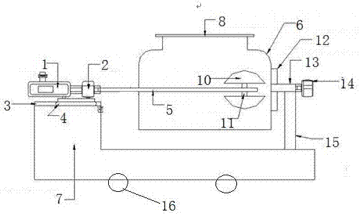
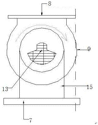
[0014] Embodiment 1: see Figure 1-Figure 2 , a self-rotating mixer, the self-rotating mixer includes a power part, a transmission shaft 5, a tank part, a mixer blade, a machine tool base, a rotating part and a moving part, and the power part is fixed on a support part, and one end is connected to the transmission The two ends of the transmission shaft 5 are respectively connected to the power part and the mixer blade; the mixer blade 10 and part of the transmission shaft 5 are located in the tank part; the rotating part stands on one side of the tank part and is fixed on the machine tool base, so The power components include a motor 1, a reduction box 2, a sliding guide rail 3, and a sliding base 4; the motor and the reduction box are fixed on the sliding base; the sliding base is placed on the sliding guide rail. Fix the motor and reducer on the base with sliding track, so that during the stirring process, the stirring blades can be controlled to move back and forth repeated...
Embodiment 2
[0015] Example 2: see Figure 1-Figure 2 , as an improvement of the present invention, the mixer blade is fixed at the end of the transmission shaft 5 by means of the blade fixing bracket 11 . Each paddle has an independent fixing bracket. If damage occurs during production, only one of the blades needs to be replaced, which greatly reduces maintenance costs compared to traditional agitators.
Embodiment 3
[0016] Embodiment 3: see Figure 1-Figure 2 , as an improvement of the present invention, the rotating part includes a tank fixing seat 12, a tank rotating bearing 13, a rotating motor 14 and a sealed tank bracket 15; the tank rotating bearing is fixed to the tank by means of the tank fixing seat The surface of the body; the output end of the rotating motor is connected with the rotating bearing of the tank body and arranged on the support of the sealed tank; the support of the sealed tank is fixed on the base of the machine tool. The rotating part of the tank used in this design scheme is simple and compact in design. When working, the tank body and the stirring blades can rotate in the same direction, thereby reducing the working load of the blades and prolonging the service life of the blades; and the tank body and the stirring blades can be rotated in reverse to increase the friction between the raw materials in the tank and the blades Force, improve cutting efficiency, r...
PUM
 Abstract
Description
Claims
Application Information
 - R&D
- Intellectual Property
- Life Sciences
- Materials
- Tech Scout
- Unparalleled Data Quality
- Higher Quality Content
- 60% Fewer Hallucinations
Browse by: Latest US Patents, China's latest patents, Technical Efficacy Thesaurus, Application Domain, Technology Topic, Popular Technical Reports.
© 2025 PatSnap. All rights reserved.Legal|Privacy policy|Modern Slavery Act Transparency Statement|Sitemap|About US| Contact US: help@patsnap.com


