Positioning marking method, device and system of in-built part of rotating shell

A technology for positioning marks and the inner surface of the shell, applied in workshop equipment, manufacturing tools, etc., can solve the problems of occlusion of the projection path and low spatial opening, and achieve the effect of improving positioning accuracy, realizing high-precision positioning, and eliminating alignment errors.

Active Publication Date: 2017-06-30
AEROSPACE RES INST OF MATERIAL & PROCESSING TECH +1
View PDF8 Cites 13 Cited by
  • Summary
  • Abstract
  • Description
  • Claims
  • Application Information

AI Technical Summary

Problems solved by technology

It is not suitable for the environment where the opening of the space is not high, the projection path w

Method used


Image

  • Positioning marking method, device and system of in-built part of rotating shell
  • Positioning marking method, device and system of in-built part of rotating shell
  • Positioning marking method, device and system of in-built part of rotating shell

Examples


specific Embodiment

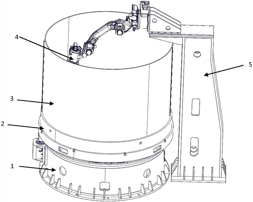
[0119] The device comprises a numerical control turntable 1, a positioning disc 2, a robot 4 (joint arm robot), an auxiliary tooling 5, a robot end clamping mechanism 6, a laser scanner 7, and a jetting dock 8. Among them, the rotary housing 3 is fixed on the positioning disc 2 through the positioning pin 9, and the positioning joint 10 is installed on the positioning disc 2, and the positioning disc 2 is installed on the numerical control turntable 1 through the positioning joint 10, and the positioning is realized by the positioner 11. Disc positioning, tension. Thereby, the coaxiality between the rotary housing 3 and the numerically controlled turntable 1 is ensured, and alignment in this way is high in efficiency and simple in operation, and there is no need to continuously adjust the position of the rotary housing 3 on the numerically controlled turntable 1 by using a traditional dial indicator.

[0120] After the rotary housing 3, the positioning disk 2 and the numerical...


PUM


Abstract

The invention provides a positioning marking method, device and system of an in-built part of a rotating shell, and relates to the technical field of assembling. The positioning marking method comprises the steps that laser scanning is conducted on the inner surface of the rotating shell, so that a shell inner surface model is obtained; a preset assembling model is adjusted according to the obtained inner surface model, so that a practical assembling model is obtained; position data of the part in the rotating shell are determined according to the practical assembling model; and positioning marking is conducted on the part in the rotating shell according to the position data, so that automatic positioning marking of the part is achieved. The whole marking process is accomplished by an operator through a computer, and manual and mechanical measurement and other manual labor are not required.

Description

technical field [0001] The invention discloses a method, a device and a system for positioning and marking internal parts of a rotary housing, belonging to the technical field of assembly. Background technique [0002] For the positioning method of the internal parts of the rotary shell, the domestic traditional method is to use mechanical measuring tools such as steel rulers and vernier calipers to mark lines to ensure. This method of scribing is low in cost and does not require high operator experience, but it is prone to human errors, and most of the angle dimensions are converted into arc lengths, which are confirmed by measuring the arc length with a steel ruler, and the error is relatively large. There is no ability to predict in advance whether there will be interference in the later assembly process. In addition, the positioning accuracy of parts is ensured by assembling special parts positioning tooling and assembly jigs. This method has a long cycle and requires ...

Claims


Application Information

Patent Timeline
IPC IPC(8): B25H7/04
Inventor 张鹏闻伟王蕴宝梅立王新
Owner AEROSPACE RES INST OF MATERIAL & PROCESSING TECH
Why Eureka
Try Eureka