Differential transceiver RF switch and RF terminal

A transmit port and switch technology, which is applied in the field of differential transceiver RF switches and RF terminals, can solve problems such as limited isolation, low isolation of RF switches, and noise interference of RF terminals, and achieve the effect of improving isolation

Active Publication Date: 2020-01-17
SHANGHAI HUAHONG GRACE SEMICON MFG CORP
View PDF8 Cites 0 Cited by
  • Summary
  • Abstract
  • Description
  • Claims
  • Application Information

AI Technical Summary

Problems solved by technology

[0004] Due to the non-ideality of the device, the differential transceiver RF switch has a certain insertion loss, and the isolation is also limited, and it is difficult to achieve high isolation characteristics under low insertion loss
Especially when in the transmit mode, the low isolation of the differential transceiver RF switch may cause noise interference to the RF terminal

Method used


Image

  • Differential transceiver RF switch and RF terminal
  • Differential transceiver RF switch and RF terminal
  • Differential transceiver RF switch and RF terminal

Examples


Embodiment Construction

[0027] As mentioned in the background section, due to the non-ideality of the device, the differential transceiver RF switch has a certain insertion loss, and the isolation is limited, and it is difficult to achieve high isolation characteristics under low insertion loss. Therefore, how to improve the isolation of the differential transceiver radio frequency switch on the basis of ensuring the insertion loss of the differential transceiver radio frequency switch is a problem to be solved.

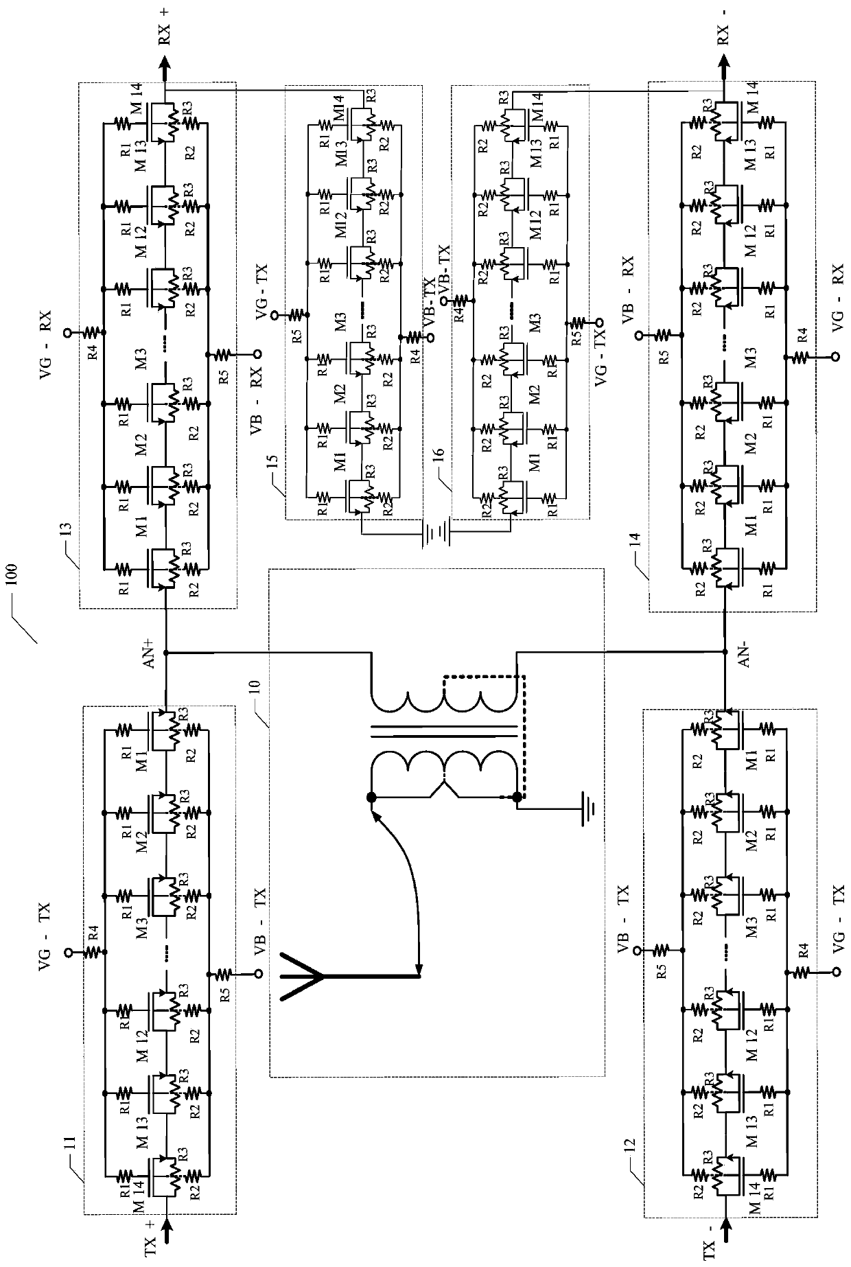
[0028] First of all, the inventor of the present application figure 1 A differential transceiver RF switch 100 shown is analyzed. Such as figure 1As shown, the differential transceiver radio frequency switch 100 may include: a transmitting port (not marked in the figure) and a receiving port (not marked in the figure), an antenna port (not marked in the figure) is arranged between the transmitting port and the receiving port , wherein the antenna port is an output port of the antenna circ...


PUM


Abstract

The invention provides a differential transceiver radio frequency switch and a radio frequency terminal. The differential transceiver radio frequency switch comprises a transmitting port and a receiving port, wherein an antenna port is formed between the transmitting port and the receiving port, a positive end of the transmitting port is connected with the positive end of the antenna port through a first switching circuit, a negative end of the transmitting port is connected with the negative end of the antenna port through a second switching circuit, the positive end of the antenna port is connected with the positive end of the receiving port through a third switching circuit, the negative end of the antenna port is connected with the negative end of the receiving port through a fourth switching circuit, both of a control end of the first switching circuit and the control end of the second switching circuit receive a first control signal, and forth of the control end of the third switching circuit and the control end of the fourth switching circuit receive a second control signal; and a fifth switching circuit coupled between the positive end of the receiving port and the negative end of the receiving port, and the control end of the fifth switching circuit receives the first control signal. By adoption of the scheme provided by the invention, the isolation of the radio frequency switch can be improved, and the circuit area can be reduced.

Description

technical field [0001] The invention relates to the field of radio frequency circuit design, in particular to a differential transceiver radio frequency switch and a radio frequency terminal. Background technique [0002] In a wireless or mobile communication system, a radio frequency switch (Radio Frequency Switch, RFSW for short) is often used to select a radio frequency channel. Taking a mobile phone as an example, a dual-pole double-throw (Dual-Pole Dual-Throw, DPDT for short) type radio frequency switch can select a channel for transmitting and receiving wireless signals of the mobile phone. The wireless signal is a differential signal, which can improve the anti-interference characteristic of data signal transmission. The DPDT radio frequency switch is generally coupled to the antenna port, and the two switch branches it includes realize the reception and transmission of wireless signals under the condition of sharing the antenna. [0003] At present, the CMOS proces...

Claims


Application Information

Patent Timeline
Patent Type & Authority Patents(China)
IPC IPC(8): H03K17/689
CPCH03K17/689
Inventor 戴若凡
Owner SHANGHAI HUAHONG GRACE SEMICON MFG CORP
Why Eureka
Try Eureka