Exhaust structure for animal houses

A technology for houses and animals, applied in animal houses, poultry cages or houses, and poultry farming, etc., can solve problems such as turbid air pollution, and achieve the effect of small space occupation, favorable for feeding, and avoiding mixed pollution.

Inactive Publication Date: 2017-07-04
余平
View PDF5 Cites 2 Cited by
  • Summary
  • Abstract
  • Description
  • Claims
  • Application Information

AI Technical Summary

Problems solved by technology

[0003] The present invention intends to provide an exhaust structure for animal houses, so as to solve the problem that existing animal houses are polluted by turbid air during ventilation and exhaust

Method used


Image

  • Exhaust structure for animal houses
  • Exhaust structure for animal houses
  • Exhaust structure for animal houses

Examples


Embodiment 1

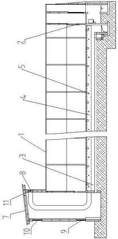
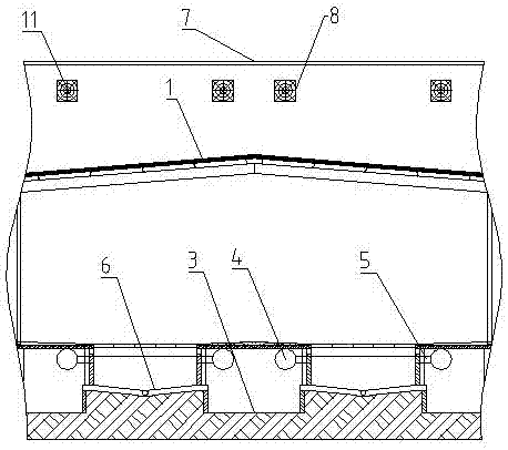
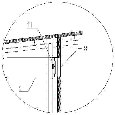
[0023] Embodiment one, basically as attached figure 1 , Figure 4 Shown: the exhaust structure of the animal house, including the breeding house body 1, and the middle part of the breeding house body 1 is provided with an indoor air inlet 2; as figure 2 As shown, the bottom of the breeding house body 1 is provided with a first ventilation channel 3 and a defecation channel 6 at intervals, the first ventilation channel 3 is provided with a second ventilation channel 4, and the second ventilation channel 4 communicates with the defecation channel 6 There is a third ventilation channel 5, and one end of the third ventilation channel 5 communicated with the defecation channel 6 is located at the upper part of the side wall of the defecation channel 6. The left and right ends of the breeding house body 1 are all provided with ventilation building 7, and the side wall of ventilation building 7 is provided with air inlet and air outlet 8, as image 3 As shown, an exhaust fan 11 is...

Embodiment 2

[0028] Embodiment two, the difference between this embodiment and embodiment one is that the indoor air inlet 2 is located at the right end of the breeding house body 1, the ventilation building 7 is located at the left end of the breeding house body 1, the bottom of the defecation channel 6 is V-shaped, and the first ventilation The bottom of the road 3 is lower than the bottom of the defecation channel 6, the second air channel 4 and the third air channel 5 are plastic pipes, and one end of the third air channel 5 is connected to the second air channel 4 by a three-way pipe, and the other end is connected to the second air channel 4. It is fixed on the side wall of the excrement channel 6 by concrete. The second ventilation channel 4 is arranged in a serpentine tubular shape in the ventilation building 7, which can increase the residence time of the turbid air in the ventilation building 7, so that the outdoor air entering the ventilation building 7 is fully combined with the...


PUM


Abstract

The invention discloses an exhaust method for animal houses in the field of animal husbandry breeding. Through the installation of paralleled air channels and manure channels at the bottom of the animal houses and the installation of exhaust pipes inside the air channels, the exhaust pipes are communicated with the side wall of the manure channels; ventilating buildings are built at two ends of the animal house; the air channels are communicated with the ventilating buildings; the exhaust pipes are communicated with the outside; in this way, waste air is sucked and exhausted from the bottom of the animal houses through the exhaust pipes; at the same time, heat exchange is carried out by the gas inside the exhaust pipes and the air channels. Therefore, the gas entering the animal house can be preheated or pre-cooled; on one hand, the problem that present animal houses may be polluted during ventilating or exhausting can be solved, on the other hand, the temperature of gas entering the animal houses is more suitable for the animals.

Description

technical field [0001] The invention relates to the field of animal houses, in particular to an exhaust structure for animal houses. Background technique [0002] The animal house is a place for raising animals. Using the principles of animal ecology, the environment and conditions suitable for animal survival are studied. Usually, the environmental conditions of the animal house need to be well ventilated, and the conditions such as temperature, humidity, and light are suitable. Among many conditions, because the existing animal houses are all airtight environments, the ventilation system either uses modern equipment such as fans and air conditioners, which is expensive, or the ventilation effect is poor. Therefore, the inventor has previously developed a centralized management system. Animal houses, such as Chinese Patent Publication No.: CN205546846U, include a breeding house body, and ventilation buildings are arranged on opposite ends above the breeding house body, and ...

Claims


Application Information

Patent Timeline
Patent Type & Authority Applications(China)
IPC IPC(8): A01K1/00A01K1/01A01K31/04
CPCA01K1/0047A01K1/01A01K31/04
Inventor 余平
Owner 余平
Why Eureka
Try Eureka