Precision instrument polishing equipment

A technology of precision instruments and equipment, applied in the field of precision instruments, can solve the problems of unsatisfactory precision requirements, poor polishing quality, poor rigidity of polishing knives, etc., and achieve the effects of low production cost, convenient and fast polishing, and stable operation

Inactive Publication Date: 2017-07-04
众顶(广州)科技有限公司
View PDF7 Cites 0 Cited by
  • Summary
  • Abstract
  • Description
  • Claims
  • Application Information

AI Technical Summary

Problems solved by technology

[0002] Precision instruments require a high degree of polishing, and the inner hole of the instrument initially polished often leaves spiral knife lines, and the finish is very poor. It is very difficult to eliminate knife lines by honing. Boring is limited by the depth and diameter of the hole, so for It is difficult to grind and polish the hole wall with traditional mechanical polishing methods for slender holes. A slender polishing knife is required to polish slender holes. This kind of polishing knife has poor rigidity and is easy to break, and the polishing strength is not enough to achieve polishing. Quality requirements, the traditional polishing equipment is that the instrument is fixed through the workbench at the bottom, and the polishing knife is driven by the first power device on the top. During the polishing process, more debris is often produced, and the slender polishing knife is grinding It is easy to shake sometimes, which will lead to poor polishing effect and cannot meet the existing requirements for instrument accuracy.

Method used


Image

  • Precision instrument polishing equipment
  • Precision instrument polishing equipment
  • Precision instrument polishing equipment

Examples


Embodiment Construction

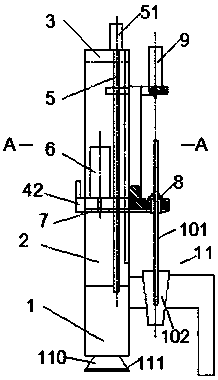
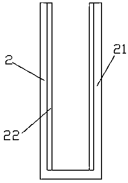
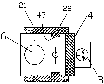
[0022] Such as Figure 1-Figure 7 As shown, a kind of precision instrument polishing equipment of the present invention comprises machine base 1, vertical rod 2, support plate 3, work frame 4, moving device, first rotating power device, instrument fixing device and polishing knife 11, described The vertical rod 2 is fixedly arranged on the left side of the upper surface of the machine base 1, the vertical rod 2 includes side plates 21 arranged front and back, the support plate 3 is fixed on the upper end of the vertical rod 2, and on the side The inner side of the plate 21 is provided with a slide rail protruding bar 22 extending in the up and down direction, the left part of the work frame 4 is arranged between the side plates 21 arranged front and back, and the moving device includes an up and down moving device 51 and a lead screw 5. The up and down movement device 51 is fixed above the support plate 3, and the conduction shaft of the up and down movement device 51 runs thr...


PUM


Abstract

The invention discloses precision instrument polishing equipment which comprises a machine base (1), an upright pole (2), a support plate (3), a framework (4), a motion device, a first swirling power device, an instrument fixing device and a polishing cutter (11), wherein the upright pole (2) is fixedly arranged on the left side of the upper surface of the machine base (1) and comprises side plates (21) which are arranged in front and back; the support plate (3) is fixed at the upper end of the upright pole (2); a sliding rail bulging bar (22) which extends upwards and downwards is arranged on the inner sides of the side plates (21); the left side part of the framework (4) is arranged between the side plates (21) arranged in front and back; and the motion device comprises an up-down motion device (51) and a lead screw (5). The precision instrument polishing equipment has a compact overall structure, is low in production cost, is safe and reliable to use, and is stable to operate.

Description

technical field [0001] The invention relates to the field of precision instruments, in particular to a polishing equipment for precision instruments. Background technique [0002] Precision instruments require a high degree of polishing, and the inner hole of the instrument initially polished often leaves spiral knife lines, and the finish is very poor. It is very difficult to eliminate knife lines by honing. Boring is limited by the depth and diameter of the hole, so for It is difficult to grind and polish the hole wall with traditional mechanical polishing methods for slender holes. Slender polishing knives are required for polishing slender holes. This type of polishing knife has poor rigidity and is easy to break, and the polishing strength is not enough to achieve polishing. Quality requirements, the traditional polishing equipment is that the instrument is fixed through the workbench at the bottom, and the polishing knife is driven by the first power device on the top....

Claims


Application Information

Patent Timeline
Patent Type & Authority Applications(China)
IPC IPC(8): B24B29/08B24B41/06B24B41/02B24B47/12
CPCB24B29/08B24B41/02B24B41/06B24B47/12
Inventor 黄陈凯
Owner 众顶(广州)科技有限公司
Why Eureka
Try Eureka