
Dust suction mechanism of printing device for printed fabrics

A vacuuming mechanism and printing technology, applied in the field of printing devices and vacuuming mechanisms for printed fabrics, can solve the problems of increasing the fabric pollution area, hindering the adhesion of printing patterns, affecting the printing quality, etc., so as to improve work stability and reduce obstacles. , to ensure the effect of stability

Active Publication Date: 2019-05-14
ZHEJIANG XIANYU FIBER WEAVING & DYEING GARMENT CO LTD
View PDF13 Cites 0 Cited by
  • Summary
  • Abstract
  • Description
  • Claims
  • Application Information

AI Technical Summary

Problems solved by technology

[0004] There is a problem with the above-mentioned equipment: the fabric is not vacuumed before spraying, resulting in the contact of dust and water to increase the pollution area of ​​the fabric, hindering the adhesion of the printed pattern, and affecting the printing quality

Method used


Image

  • Dust suction mechanism of printing device for printed fabrics
  • Dust suction mechanism of printing device for printed fabrics
  • Dust suction mechanism of printing device for printed fabrics

Examples


Embodiment Construction

[0032] The following are specific embodiments of the present invention and in conjunction with the accompanying drawings, the technical solutions of the present invention are further described, but the present invention is not limited to these embodiments.

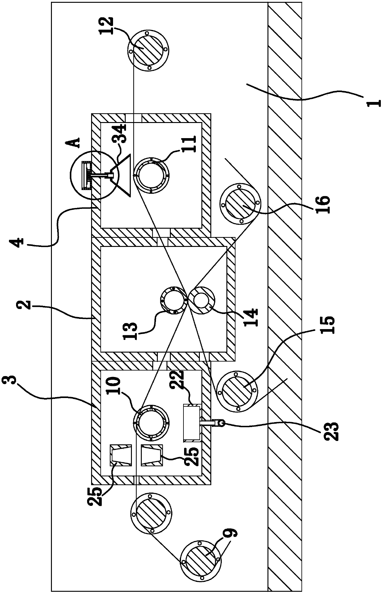
[0033] Such as figure 1 As shown, the printing device of this printed fabric is composed of frame 11, printing chamber 2, humidification and dust removal chamber 3, drying chamber 4, cloth feeding mechanism, paper feeding mechanism, exhaust fan 5, heater 6, vacuum cleaner 7, etc., water pump 8 and so on. Among them, the heater 6 and the vacuum cleaner 7 are existing products, such as a heater [application number: 201220183279.8] and a vacuum cleaner [application number: 201280008849.2] disclosed in the Chinese patent database.

[0034] Specifically, the longitudinal section of the bracket 32 ​​is L-shaped, and the bracket 32 ​​includes a vertically arranged installation part 1 and a horizontally arranged installation part...


PUM


Abstract

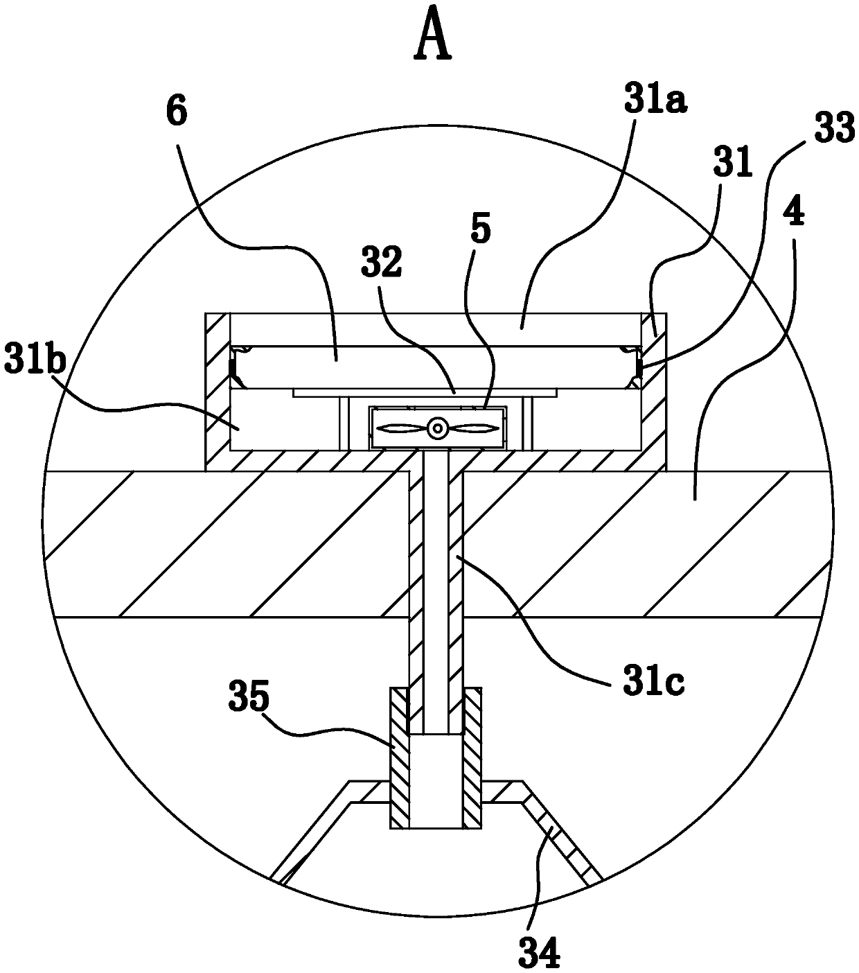
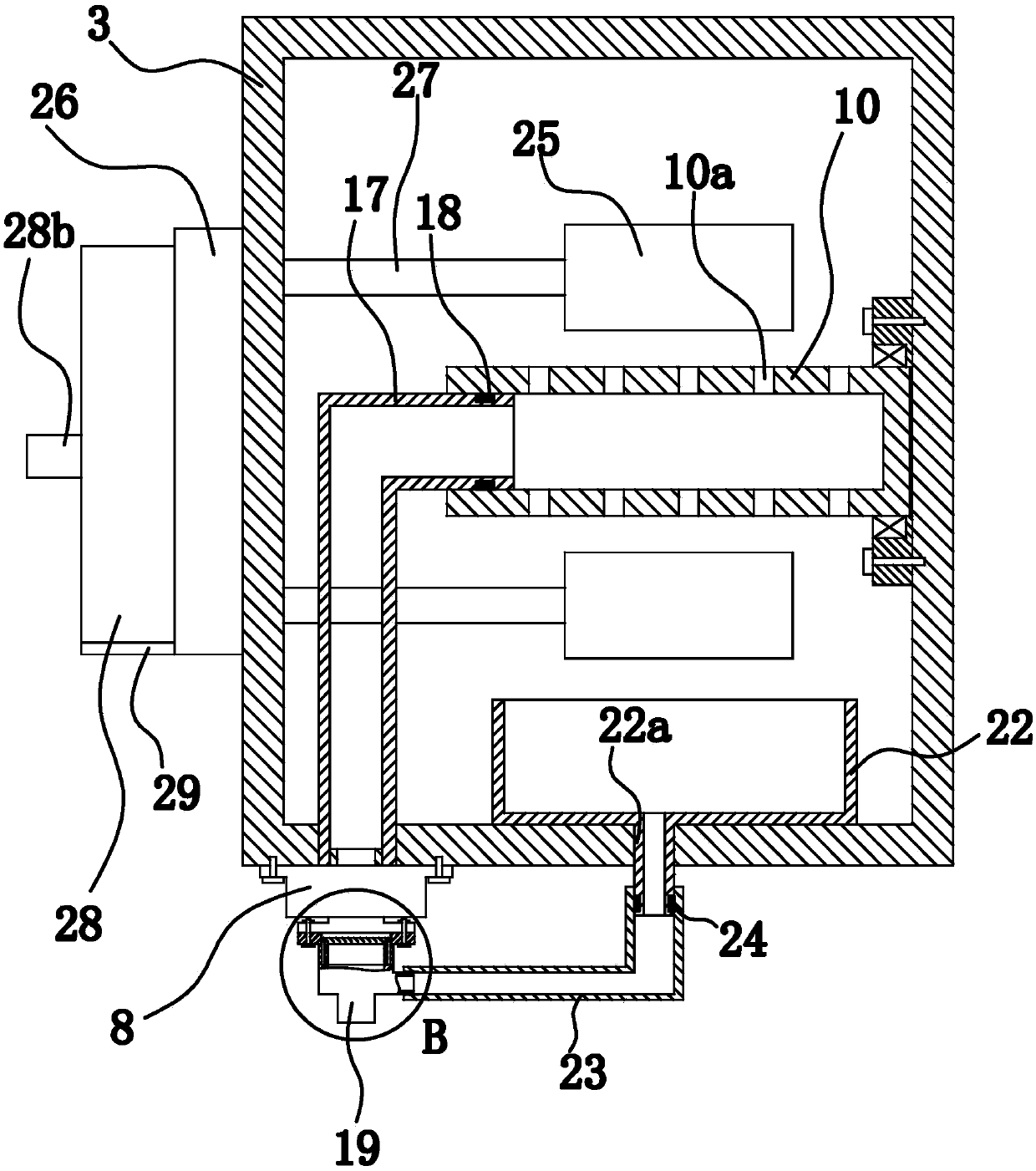
The invention provides a dust collection mechanism of a printed fabric printing device, which belongs to the technical field of machinery and solves the problem of bad printing quality of an existing printing device. According to the dust collection mechanism, the printed fabric printing device comprises a humidification and dust collection chamber and a cloth guide roller I, wherein the cloth guide roller I is arranged in the humidification and dust collection chamber, and a cloth inlet which is used for fabrics to enter is formed in the humidification and dust collection chamber; the dust collection mechanism comprises two gas collection barrels, wherein the gas collection barrels are arranged in the humidification and dust collection chamber, the gas collection barrels are located between the cloth inlet and the cloth guide roller I, the two gas collection barrels are symmetrically arranged along a fabric conveying direction, openings of the gas collection barrels face towards fabrics, the inner side walls of the gas collection barrels are tapered gas guide surfaces, a dust collector and a gas collection box with a closed inner cavity are installed on the outer side of the humidification and dust collection chamber, two dust inlets and a dust outlet which enable the inner cavity to communicate with the outside are formed in the gas collection box, the two dust inlets respectively communicate with inner cavities of the two gas collection barrels through connecting pipes, and an inlet of the dust collector communicates with the dust outlet. The dust collection mechanism has the advantage of good printing quality.

Description

technical field [0001] The invention belongs to the technical field of machinery, and relates to a printing device for printed fabrics, in particular to a dust suction mechanism of the printing device for printed fabrics. Background technique [0002] The development of China's printing equipment industry has become a global industry so far, and it has been in line with international standards in terms of production methods, technological innovation, and talent training models. [0003] At present, there are all kinds of thermal transfer printing equipment on the market, and the most common one is roller thermal transfer printing. The equipment involved in roller heat transfer printing, such as a fabric printing equipment disclosed in the Chinese patent library [application number: 201620450538.7; authorized announcement number: CN 205736373U], includes fabric unwinding rollers, humidification room, printing room, drying room , a fabric rewinding roller and a printing devic...

Claims


Application Information

Patent Timeline
Patent Type & Authority Patents(China)
IPC IPC(8): B41F23/00B41F23/02
CPCB41F23/002B41F23/02
Inventor 李柏青陈永江
Owner ZHEJIANG XIANYU FIBER WEAVING & DYEING GARMENT CO LTD
Learn More