Concrete slant component upper supporting system and construction method for same

A support system and concrete technology, which is applied to the preparation of building components on site, pillars, building structures, etc. Uniform, improve connection strength, improve the effect of overall stability

Inactive Publication Date: 2017-07-04
ZHONGTIAN CONSTR GROUP
View PDF6 Cites 5 Cited by
  • Summary
  • Abstract
  • Description
  • Claims
  • Application Information

AI Technical Summary

Problems solved by technology

[0004] The technical problem to be solved by the present invention is to provide an upper support system for concrete inclined members, which can solve the problems of punching damage of the inclined plate, local instability of the vertical rod and overall instability of the formwork during the formwork support of the inclined plate.

Method used


Image

  • Concrete slant component upper supporting system and construction method for same
  • Concrete slant component upper supporting system and construction method for same
  • Concrete slant component upper supporting system and construction method for same

Examples


Embodiment 1

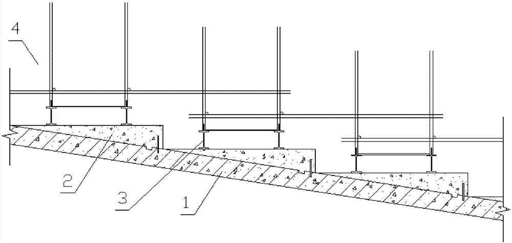
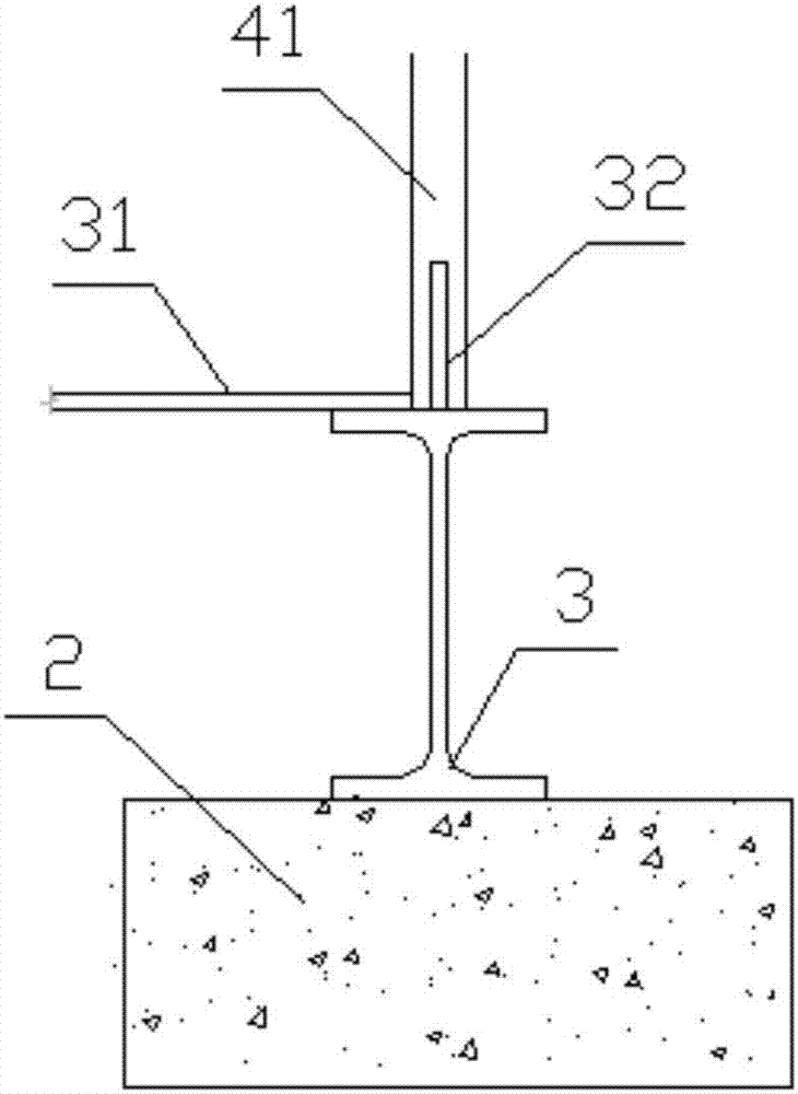
[0025] Example 1, such as Figure 1 to Figure 3 As shown, an upper support system of a concrete inclined member is built on the completed reinforced concrete inclined member 1, which includes several levels of concrete steps 2 arranged along the slope of the reinforced concrete inclined member. A full-length I-beam 3 is placed on the concrete steps 2, and a support frame 4 is set up above the I-beam, and the support pole of the support frame is supported on the I-beam.

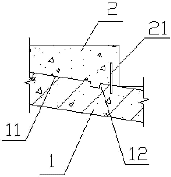
[0026] Wherein, the slope of the reinforced concrete inclined member 1 is provided with a chiseled surface 11 combined with the concrete steps 2, and further, the slope of the reinforced concrete inclined member is provided with an anti-slip surface integrated with the concrete steps. The shear pressure groove 12 and the concrete steps 2 are poured with vertical inserts 21 inserted into the inclined members of reinforced concrete. The above technical measures improve the connection strength of the contact sur...

Embodiment 2

[0038] Example 2, such as Figure 4 As shown, the difference from Embodiment 1 is that a threaded sleeve is pre-embedded at the position corresponding to the concrete step on the slope of the reinforced concrete inclined member, and a screw rod 22 is screwed in the threaded sleeve, and the screw rod is fixed with a concrete step by a nut. Pouring the integrated stiffener plate 23. In order to further enhance the joint force to the concrete steps 2, the stiffener plate 23 can be provided with stiffeners vertically. Therefore, the connection strength of the contact surface is further improved, and the overall stability of the support frame is improved

[0039] In addition, the concrete steps are pre-embedded with positioning sleeves corresponding to the positions of the I-beams, and the I-beams are provided with positioning ribs inserted into the positioning sleeves to achieve rapid positioning of the I-beams and ensure the stability of the I-beams.


PUM


Abstract

The invention discloses a concrete slant component upper supporting system and a construction method for the same. The concrete slant component upper supporting system is built on a completed reinforced concrete slant component and comprises a plurality of concrete steps arranged on a slope of the reinforced concrete slant component; the slope of the reinforced concrete slant component is provided with anti-shearing slots and vertical insertion ribs cast with the concrete steps; each concrete step is provided with elongated I-shaped steel; a supporting rack is built over the I-shaped steel; and supporting stand columns of the supporting rack are supported on the I-shaped steel. With arrangements of the concrete steps and the increase of the I-shaped steel, concentrated force of the supporting rack can be converted into uniform-distribution force, so damage to a top plate surface layer can be eliminated; and a cross section of each stand column is evenly stressed, so perpendicularity can be guaranteed and local stability of the column member can be enhanced.

Description

technical field [0001] The present invention relates to building construction technology. Background technique [0002] In the construction of building structures, when the ramp of the underground garage is a ramp and the roof of the basement is an oblique member, the support system is usually directly supported on the inclined plate to transfer the load transmitted from the beam plate of the upper structure of the support. The structure of the supporting system on the common sloping plate is simple, or there is no method, and the vertical pole is directly supported on the roof. The problems can be imagined, mainly include: 1. The vertical rods directly supported on the sloping plate will generate concentrated force on the sloping plate, and it is impossible to simply set up the backing plate to accept and spread, and produce punching force on the concrete that has not reached the design strength , resulting in damage to the surface of the sloping slab; 2. The eccentric for...

Claims


Application Information

Patent Timeline
Patent Type & Authority Applications(China)
IPC IPC(8): E04G13/00E04G25/00
CPCE04G13/00E04G25/00
Inventor 刘玉涛沈映周巧君龚永庆
Owner ZHONGTIAN CONSTR GROUP
Why Eureka
Try Eureka