Pneumatic actuating mechanism for one-way damping valve

A pneumatic actuator, one-way damping technology, applied in engine components, valve operation/release devices, valve details, etc., can solve the problems of reduced energy efficiency of catalytic cracking units, poor sealing performance of one-way damping valves, mechanical collisions, etc. , to avoid the excessive pressure loss of the pipeline, increase the closing torque, and close the zero leakage.

Active Publication Date: 2017-07-04
BC P INC CHINA NAT PETROLEUM CORP +1
View PDF5 Cites 3 Cited by
  • Summary
  • Abstract
  • Description
  • Claims
  • Application Information

AI Technical Summary

Problems solved by technology

[0004] In the process of realizing the present invention, the inventor found that there are at least the following problems in the prior art: the existing two-position pneumatic actuator makes the one-way damping valve in the fully open position under normal conditions, resulting in excessive pressure loss in the pipeline , leading to a decrease in the energy efficiency of the catalytic cracking unit
At the same time, when an accident occurs, the one-way damping valve usually needs to be closed within 3 seconds. If it is closed at such a fast speed, severe mechanical collisions will occur, causing damage to the sealing surface of the one-way damping valve seat, resulting in deterioration of the sealing performance of the one-way damping valve. , can not play a good role in protecting the main fan

Method used


Image

  • Pneumatic actuating mechanism for one-way damping valve
  • Pneumatic actuating mechanism for one-way damping valve
  • Pneumatic actuating mechanism for one-way damping valve

Examples


Embodiment Construction

[0043] In order to make the technical solutions and advantages of the present invention clearer, the embodiments of the present invention will be further described in detail below in conjunction with the accompanying drawings.

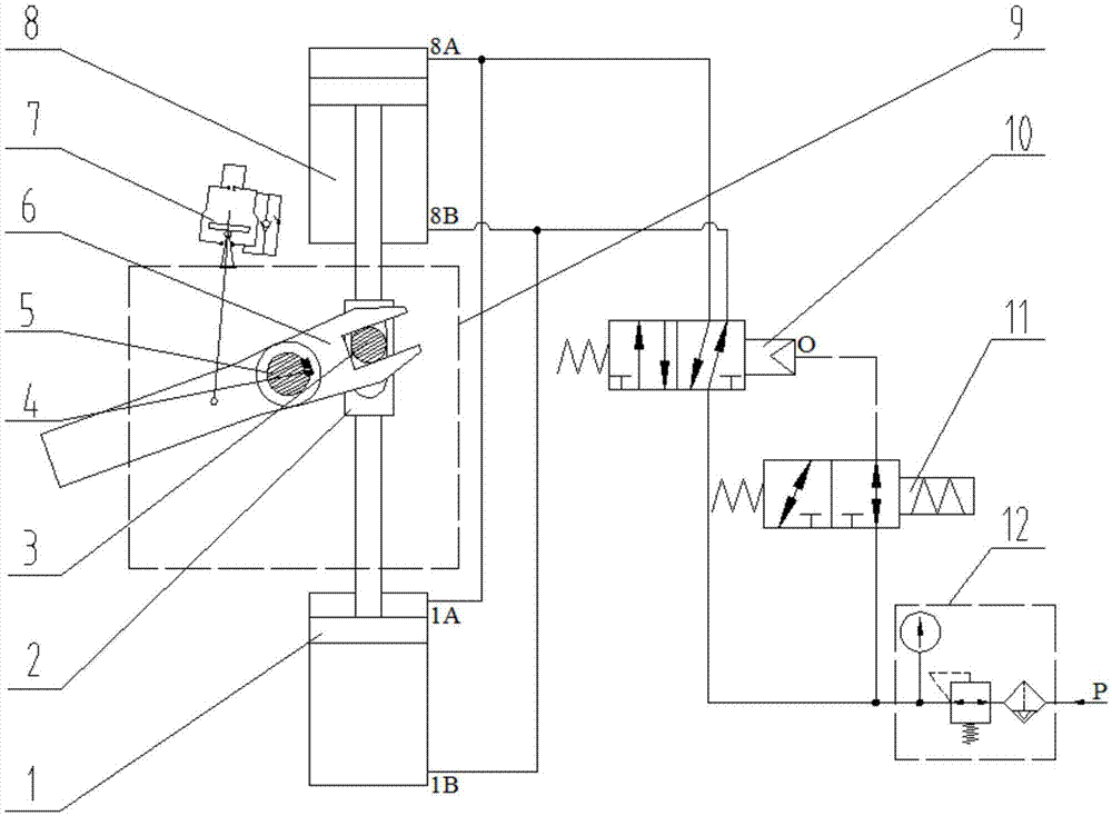
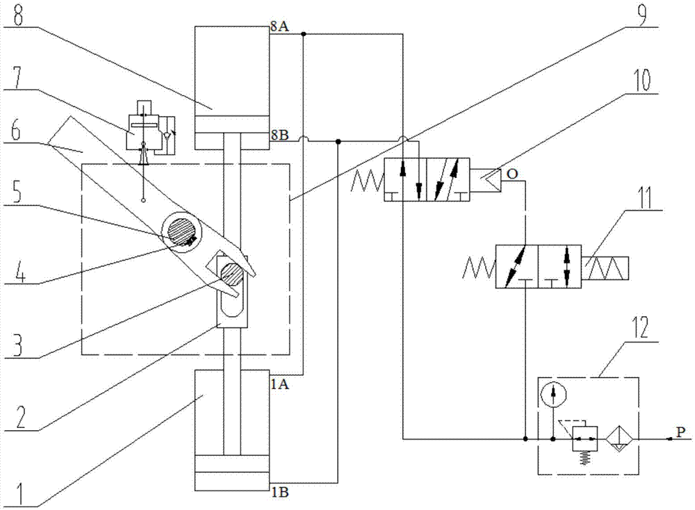
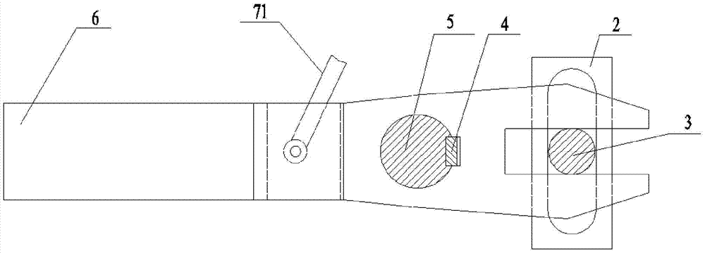
[0044] An embodiment of the present invention provides a pneumatic actuator for a one-way damping valve, the pneumatic actuator is connected to the valve shaft of the one-way damping valve, see figure 1 , and combined with figure 2 and image 3 , the pneumatic actuator includes: a first cylinder 1, a second cylinder 8, a shift fork shaft 3, a shift fork 6 and a cylinder reversing control unit; the rod of the shift fork 6 is fixedly connected to the valve shaft 5 of the one-way damping valve; The cylinder reversing control unit is used to control the reversing of the first cylinder 1 and the second cylinder 8; wherein, the pneumatic actuator also includes: a clutch mechanism 2; the clutch mechanism 2 is a cylinder, and the clutch mechanism 2 is arranged...


PUM


Abstract

The invention discloses a pneumatic actuating mechanism for a one-way damping valve and belongs to the technical field of catalytic cracking units of the petrochemical industry. The pneumatic actuating mechanism for the one-way damping valve comprises a first air cylinder, a second air cylinder, a shifting fork shaft, a shifting fork and an air cylinder reversing control unit. The rod portion of the shifting fork is fixedly connected with a valve shaft of the one-way damping valve. The air cylinder reversing control unit is used for controlling reversing of the first air cylinder and the second air cylinder. The pneumatic actuating mechanism further comprises an engagement and disengagement mechanism which is a cylinder body. The engagement and disengagement mechanism is provided with a guide groove in the longitudinal length direction. The two ends of the engagement and disengagement mechanism are fixedly connected with a piston rod of the first air cylinder and a piston rod of the second air cylinder correspondingly. The shifting fork shaft extends into a U-shaped opening formed in the end of the shifting fork and the guide groove in the engagement and disengagement mechanism. The shifting fork shaft can slide in the U-shaped opening and can conduct linear motion in the guide groove at the same time. The pneumatic actuating mechanism can improve the energy efficiency, guarantees that the one-way damping valve is closed under an emergency condition and protects the seal face of the one-way damping valve at the same time.

Description

technical field [0001] The invention relates to the technical field of catalytic cracking devices in the petrochemical industry, in particular to a pneumatic actuator for a one-way damping valve. Background technique [0002] A one-way damping valve is usually installed on the outlet pipeline of the main fan of the catalytic cracking unit in the petrochemical industry. When an accident causes the medium in the pipeline to flow backward, the one-way damping valve is quickly closed to prevent the medium in the pipeline from being damaged by the reverse flow of the main fan. The opening and closing of the one-way damping valve mainly depends on the matching pneumatic actuator to complete it. [0003] The existing pneumatic actuator for the one-way damping valve is a two-position pneumatic actuator, which mainly includes a cylinder, a shift fork, a shift fork shaft, a solenoid valve, and corresponding gas piping. The rod of the shift fork is provided with a through hole for con...

Claims


Application Information

Patent Timeline
Patent Type & Authority Applications(China)
IPC IPC(8): F16K31/163F16K15/18
Inventor 路登明张玉峰梁宗辉江泳英冯文
Owner BC P INC CHINA NAT PETROLEUM CORP
Why Eureka
Try Eureka