
Grounding ring and reaction cavity for limiting plasma leakage

A plasma and grounding ring technology, applied in the direction of discharge tubes, electrical components, circuits, etc., can solve the problems of insufficient plasma and radio frequency leakage restrictions, non-grounding, etc., to achieve improved shielding effects, ensure air flow, and increase longitudinal distances Effect

Active Publication Date: 2017-07-04
ADVANCED MICRO FAB EQUIP INC CHINA
View PDF3 Cites 8 Cited by
  • Summary
  • Abstract
  • Description
  • Claims
  • Application Information

AI Technical Summary

Problems solved by technology

[0003] In the prior art, the downward confinement of the plasma in the reaction chamber is realized by a plasma confinement ring, but considering the processing limitations and aging of the insulating layer (currently yttrium oxide) on the metal surface of the plasma confinement ring The problem is that the confinement ring is currently an ungrounded floating potential, so its confinement of the plasma only limits the mean free path in terms of physical size, and there is no electric field confinement, so there is insufficient confinement of the plasma and radio frequency leakage. question

Method used


Image

  • Grounding ring and reaction cavity for limiting plasma leakage
  • Grounding ring and reaction cavity for limiting plasma leakage
  • Grounding ring and reaction cavity for limiting plasma leakage

Examples


Embodiment Construction

[0039] The present invention will be further elaborated below by describing a preferred specific embodiment in detail in conjunction with the accompanying drawings.

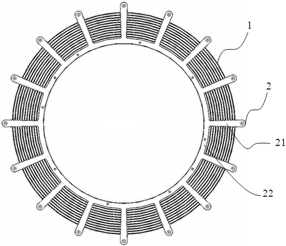
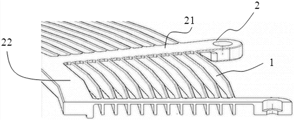
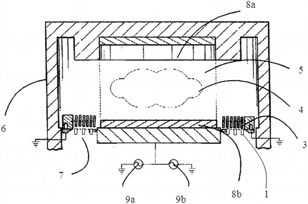
[0040] A grounding ring to limit plasma leakage, such as image 3 As shown in , it is arranged in a reaction chamber cavity 6, which contains a confinement ring 3, and the confinement ring 3 comprises a plurality of concentric rings; as figure 1 , 2 As shown, the grounding ring includes a plurality of concentric grounding rings 1 with gradually increasing radii to form a dense ring structure, and the grounding ring is located below the confinement ring 3; every two adjacent concentric grounding rings 1 The spacing between them is equal, and its spacing is twice the spacing between two adjacent concentric rings on the confinement ring 3, that is, if the spacing between adjacent concentric rings of the confinement ring 3 is 1.5mm, the phase of the grounding ring The distance between adjacent concentric grounding ...


PUM


Abstract

The invention discloses a grounding ring for limiting plasma leakage. The grounding ring is arranged in a reaction cavity, the reaction cavity comprises a limitation ring, the grounding ring is arranged below the limitation ring and comprises a plurality of concentric grounding round rings with radius gradually increased, the distance between each two adjacent concentric grounding round rings is equal and is two times of the distance between two adjacent concentric round rings on the limitation ring, and each concentric grounding round ring is arranged right below the corresponding concentric round ring on the limitation ring. The grounding ring has the advantages that the distance between adjacent ring gaps of the grounding ring is two times the distance between adjacent concentric round rings of the limitation ring, and air flow quantity is ensured; and on the other hand, a radial interface is similar to the limitation ring and downwards extends, thus, the longitudinal distance of a ground potential can be increased, and the limitation effect is improved.

Description

technical field [0001] The invention relates to the technical field of plasma etching, in particular to a grounding ring for limiting plasma and radio frequency leakage and a reaction chamber thereof. Background technique [0002] In the process of plasma etching the substrate, we hope to confine the plasma and radio frequency energy to a limited etching reaction area to improve energy efficiency, avoid corrosion of the cavity caused by plasma leakage, and reduce damage to electrical signals. interference. [0003] In the prior art, the downward confinement of the plasma in the reaction chamber is realized by a plasma confinement ring, but considering the processing limitations and aging of the insulating layer (currently yttrium oxide) on the metal surface of the plasma confinement ring The problem is that the confinement ring is currently a floating potential that is not grounded, so its confinement of the plasma only limits the mean free path in terms of physical size, a...

Claims


Application Information

Patent Timeline
IPC IPC(8): H01J37/32
CPCH01J37/32431H01J37/32458H01J37/32798
Inventor 吴磊梁洁叶如彬浦远杨金全徐朝阳
Owner ADVANCED MICRO FAB EQUIP INC CHINA
Learn More