Direct-current bias isolation grounding system based on capacitor

An isolation grounding, DC bias technology, applied in the direction of emergency protection circuit devices, electrical components, circuit devices, etc. for limiting overcurrent/overvoltage, can solve the increase of noise and vibration, increase of excitation current and harmonics, temperature rise and other problems, to achieve the effects of stable and reliable operation, high DC isolation efficiency and long service life

Inactive Publication Date: 2017-07-04
ANHUI YIGE RUIDE ELECTRIC EQUIP CO LTD
View PDF5 Cites 1 Cited by
  • Summary
  • Abstract
  • Description
  • Claims
  • Application Information

AI Technical Summary

Problems solved by technology

When the DC bias occurs in the transformer, the excitation current and harmonics of the transformer will increase sharply, the iron core will be saturated, the temperature rise, noise and vibration will increase, and high-order harmonics will be generated, which will endanger the stable operation of the transformer and

Method used


Image

  • Direct-current bias isolation grounding system based on capacitor

Examples


Embodiment Construction

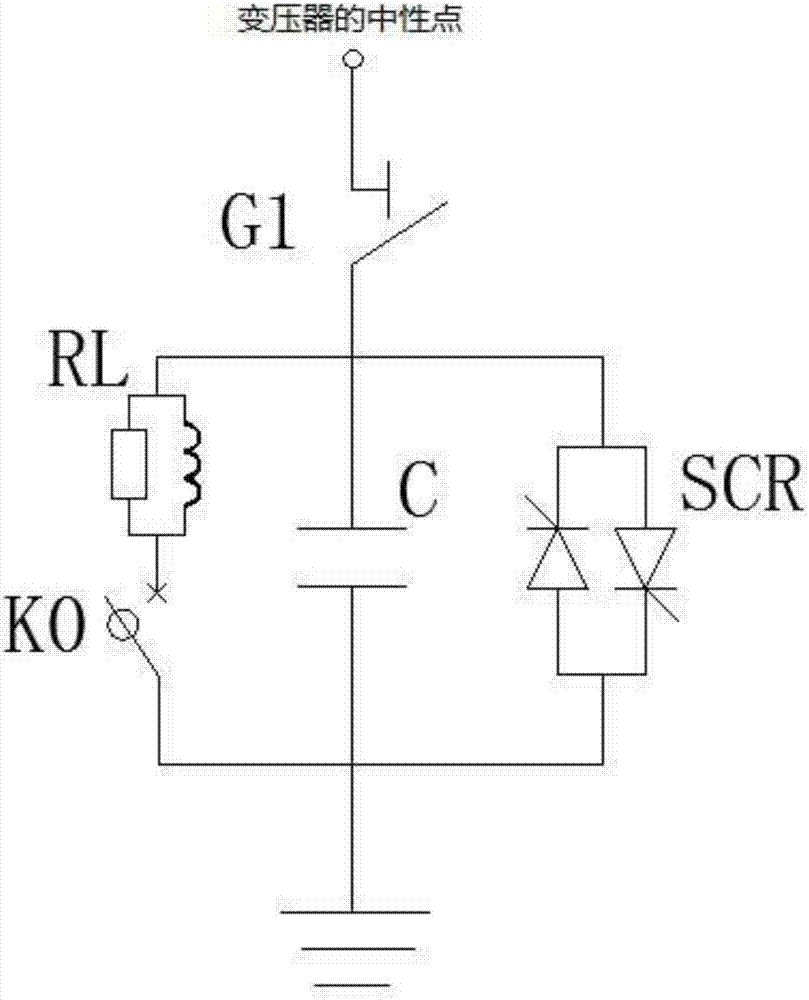
[0012] Such as figure 1 As shown, a capacitor-based DC bias isolation grounding system includes a capacitor C, an isolation switch G1 for power failure isolation, a discharge damper RL for rapid overvoltage discharge of capacitor C, and a high-speed An eddy current switch K0, and a thyristor SCR for fast protection of the capacitor C; the incoming terminal of the isolating switch G1 is connected to the neutral point of the transformer, and the outgoing terminal of the isolating switch G1 is connected to the incoming terminal of the capacitor C, The outlet end of the capacitor C is grounded; the thyristor SCR is connected in parallel with the capacitor C; the inlet end of the discharge damper RL is connected to the inlet end of the capacitor C, and the outlet end of the discharge damper RL is connected to the inlet of the high-speed eddy current switch K0 The wire ends are connected, and the outlet end of the high-speed eddy current switch K0 is connected with the outlet end of...


PUM


Abstract

The invention relates to a direct-current bias isolation grounding system based on a capacitor. The grounding system comprises a capacitor C, an isolation switch G1, a discharging damper RL, a high speed eddy current switch K0 and a silicon controlled rectifier SCR. The wire entrance end of the isolation switch G1 is connected with a neutral point of a transformer. The wire exit end of the isolation switch G1 is connected with the wire entrance end of the capacitor C. The wire exit end of the capacitor C is grounded. The silicon controlled rectifier SCR is parallelly connected with the capacitor C. The wire entrance end of the discharging damper RL is connected with the wire entrance end of the capacitor C. The wire exit end of the discharging damper RL is connected with the wire entrance end of the high speed eddy current switch K0. The wire exit end of the high speed eddy current switch K0 is connected with the wire exit end of the capacitor C. The grounding system is quite high in safety and direct current isolation efficiency; effects on an electric power system are quite small; and small impedance grounding of the neutral point of the transformer can be ensured.

Description

technical field [0001] The invention relates to the technical field of grid transformer neutral points, in particular to a capacitor-based DC bias isolation grounding system. Background technique [0002] With the development of HV and UHV DC transmission technology in my country, more and more DC projects have been put into operation. When the direct current transmission system adopts the operation mode of single pole ground return line, the current is injected into the ground through the ground pole, forming a constant direct current field in the soil of the pole site, and the AC substations and power plants distributed near the direct current pole are in different direct current conditions. At the potential point, there is a DC potential difference between the main wiring ground grids in each station. If there are AC lines connected between the two stations, and the neutral points of the main transformers of the two stations are directly grounded, the main grounding ne...

Claims


Application Information

Patent Timeline
IPC IPC(8): H02H9/02H02H9/04
CPCH02H9/02H02H9/045
Inventor 王川张国勇宋安超
Owner ANHUI YIGE RUIDE ELECTRIC EQUIP CO LTD
Why Eureka
Try Eureka