Supergravity waste gas treatment device, waste gas treatment circulating system and desulphurization and dust removal method

The technology of a waste gas treatment device and a circulation system is applied in the field of flue gas purification to achieve the effect of improving the effect of dust removal and desulfurization, improving the promotion value and increasing the specific surface area.

Pending Publication Date: 2017-07-07
YANCHENG INST OF TECH
View PDF5 Cites 7 Cited by
  • Summary
  • Abstract
  • Description
  • Claims
  • Application Information

AI Technical Summary

Problems solved by technology

[0005] The present invention provides a high-gravity waste gas treatment device, a waste gas treatment circulation system and a desulfurization and dust removal method, aiming to solve the above-mentioned problems existing in the high-gravity waste gas treatment device, waste gas treatment circulation system and desulfurization and dust removal method in the prior art

Method used


Image

  • Supergravity waste gas treatment device, waste gas treatment circulating system and desulphurization and dust removal method
  • Supergravity waste gas treatment device, waste gas treatment circulating system and desulphurization and dust removal method
  • Supergravity waste gas treatment device, waste gas treatment circulating system and desulphurization and dust removal method

Examples


Embodiment 1

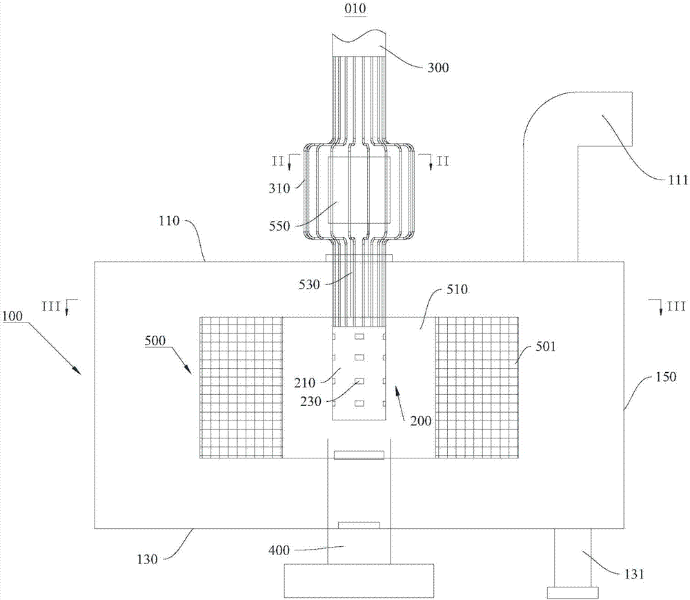
[0041] This embodiment provides a high-gravity exhaust gas treatment device, please refer to figure 1, this high-gravity waste gas treatment device includes a housing 100 , a spraying device 200 , a lye delivery pipe 300 and a waste gas pipe 400 .

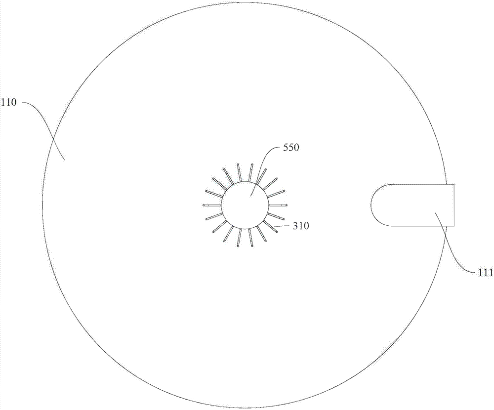
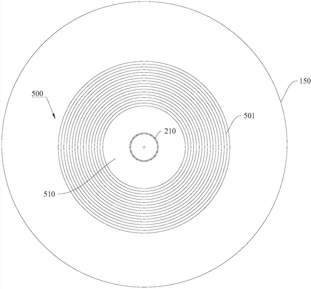
[0042] see figure 1 with figure 2 , the casing 100 is a cylindrical sealed casing, and the casing 100 includes a first surface 110 , a second surface 130 , and a side surface 150 that are oppositely arranged. The lye delivery pipe 300 passes through the center of the first surface 110 and is sealed and connected with the housing 100 , through which the lye delivery pipe 300 can deliver lye into the housing 100 . One end of the lye delivery pipe 300 close to the housing 100 is divided into a plurality of sub-pipes 310 , and the middle of the sub-pipes 310 forms a rotating accommodating space, and the rotating accommodating space can accommodate rotating components for the packing layer 500 to rotate. A lye spraying device 200 is...

Embodiment 2

[0051] This embodiment provides a waste gas treatment circulation system 001, please refer to Figure 4 , this exhaust gas treatment circulation system 001 includes a lye circulation unit 020 and the high-gravity exhaust gas treatment device in Embodiment 1.

[0052] The lye used in this embodiment is NaOH solution. The desulfurization reaction of lye in the supergravity waste gas treatment device is as follows:

[0053] 2NaOH+SO 2 →Na 2 SO 3 +H 2 o

[0054] Na 2 SO 3 +SO 2 +H 2 O→2NaHSO 3

[0055] After the lye is desulfurized, it forms a large amount of Na 2 SO 3 and NaHSO 3 The waste lye, and the waste lye can be reused through the lye circulation unit 020, and the lye is formed after reuse for the desulfurization and dust removal of the supergravity waste gas treatment device.

[0056] The lye circulation unit 020 includes a regeneration pool 021 , which is connected to the supergravity waste gas treatment device and can accept the waste lye discharged from ...


PUM

PropertyMeasurementUnit
particle diameteraaaaaaaaaa

Abstract

The invention provides a supergravity waste gas treatment device, a waste gas treatment circulating system and a desulphurization and dust removal method, and belongs to the field of flue gas purification. The supergravity waste gas treatment device comprises an alkali liquor spray device, an alkali liquor delivery pipe used for alkali liquor input and a waste gas pipe used for waste gas input; the alkali liquor spray device comprises a center pipe and multiple spray through holes, the center pipe is connected with the alkali liquor delivery pipe, and the spray through holes are formed in the outer wall of the center pipe; a waste gas pipe outlet and the center pipe are coaxial. Waste gas coming out of the waste gas pipe is subjected to first dust removal and desulphurization directly through an atomization area formed by the alkali liquor spray device, and the very high efficiency is achieved. The waste gas treatment circulating system comprises the supergravity waste gas treatment device and an alkali liquor circulation part, by means of circulating utilization of alkali liquor the cost is reduced, and the automation level is improved.

Description

technical field [0001] The invention relates to the field of flue gas purification, in particular to a supergravity waste gas treatment device, a waste gas treatment circulation system and a desulfurization and dust removal method. Background technique [0002] PM2.5 is particulate matter that can enter the lungs. Because it is rich in a large amount of toxic and harmful substances and stays in the atmosphere for a long time, it is a serious hazard to human health and the quality of the atmospheric environment. The global air quality map released by the National Aeronautics and Space Administration (NASA) in September 2010 shows that the PM2.5 index in most parts of my country is much higher than the safe value. Coal burning and motor vehicle exhaust are the primary culprits of PM2.5 pollution. Strengthening the emission control of ultrafine particles from the source of industry has become the main way to solve air pollution. According to reports, in December 2016, 11 provi...

Claims


Application Information

Patent Timeline
Patent Type & Authority Applications(China)
IPC IPC(8): B01D53/78B01D53/50B01D53/96B01D47/08
CPCB01D47/08B01D53/502B01D53/504B01D53/96
Inventor 张长森管浩冯桢哲吴其胜诸华军
Owner YANCHENG INST OF TECH
Why Eureka
Try Eureka