Wedged embedded binder clip loading and unloading device

A long tail clip and embedded technology, which is applied in metal processing equipment, metal processing, manufacturing tools, etc., can solve the problems of reduced precision, wear, and difficult control of cylinder speed, so as to promote production efficiency, improve operation efficiency, and improve reliability. sexual effect

Pending Publication Date: 2017-07-07
ZHEJIANG UNIV OF TECH
View PDF13 Cites 2 Cited by
  • Summary
  • Abstract
  • Description
  • Claims
  • Application Information

AI Technical Summary

Problems solved by technology

[0004] This method of using the cylinder to drive the push plate is difficult to control the speed of the cylinder, and often hits the clamp body base and the slider at a relatively high speed, and the slope of the push plate

Method used


Image

  • Wedged embedded binder clip loading and unloading device
  • Wedged embedded binder clip loading and unloading device
  • Wedged embedded binder clip loading and unloading device

Examples


Embodiment Construction

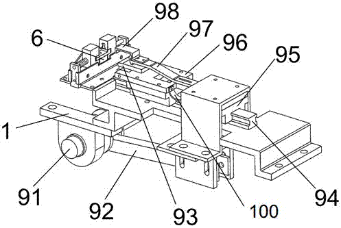
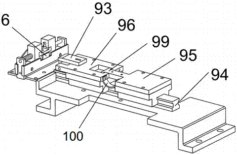
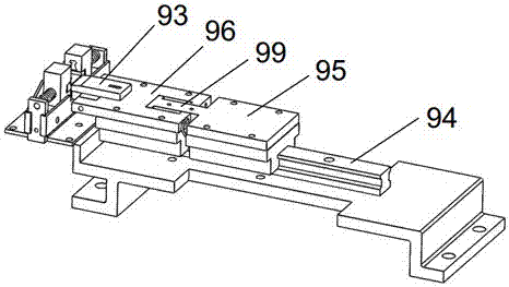
[0024] With reference to the accompanying drawings, the wedge-shaped embedded long tail clip loading and unloading device includes a frame 1, a convex bottom platform 8 is fixed on the frame, and left and right stoppers 11, 12, front and rear baffles are fixed on the convex bottom platform. Left and right slide blocks 21,22 are arranged in the slideway that left and right stoppers and front and rear baffle plates 7 form, and the inboard side of left and right slide blocks is provided with groove 25 consistent with long tail folder shape, slide block side perforation; Spring guide rod 3. One end is fixed with the stopper, and the other end is inserted into the opening 23 on the side of the slider. The spring guide rod is covered with a spring 4; the clip body base 5 is clamped between the left and right sliders, and the two sides of the clip body base are embedded in the gaps of the left and right sliders. The lower end of the clamp body base is provided with a limit block, and ...


PUM


Abstract

The invention provides a wedged embedded binder clip loading and unloading device. A convex pedestal is installed on a rack, and left and right sliding blocks are arranged in a slideway formed by left and right check blocks and front and rear baffles; a grip-body base is clamped between the left and right sliding blocks, and both sides of the grip-body base are embedded into notches of the left and right sliding blocks; the lower end of the grip-body base is provided with a stopper, and the grip-body base is fixed to the convex pedestal; a wedged block is sheathed outside the stopper of the grip-body base, and the left and right of the wedged block are provided with inclined planes; the inclined planes of the wedged block are fit to those of the left and right sliding blocks; a crank is movably connected to a rear push plate through a connecting rod, and the rear push plate and a front push plate are installed on guide rails; the rear end of the front push plate is provided with a spring sheet, and a top block is fixed to the front push plate relatively to the wedged block. In the invention, the movable wedged block is added on the basis of the original design, so that the plug-in drive that the inclined planes are driven by the existing cylinder is converted into the surface contact push of the wedged block and the top block; the operating efficiency is improved greatly through mechanical drive, and the shortcoming of cylinder drive is overcome.

Description

technical field [0001] The invention relates to a clamping and loading and unloading device for workpieces, in particular to a clamping and loading and unloading device used on an automatic assembly line for long tail clamps. Background technique [0002] The long tail folder is a widely used stationery, the assembly of the long tail folder is mainly manual assembly, the labor intensity is high during assembly, the process is repetitive and boring, and the production efficiency is low. The applicant studies the device of the long tail clamp to operate in an automatic assembly line. [0003] The CN103273450B Chinese patent applied by the applicant discloses a clamping device of a long tail clamp. The clamping device is designed with a gap between the base of the clamp body and the left and right sliders. A push plate driven by an air cylinder is used to push the The inclined surface is inserted into the gap, and the left and right sliders are pushed away by the push plate, s...

Claims


Application Information

Patent Timeline
IPC IPC(8): B23P19/00
CPCB23P19/001
Inventor 熊四昌郑启航周赟涛毛国宾
Owner ZHEJIANG UNIV OF TECH
Why Eureka
Try Eureka