Octahedral aircraft

An aircraft and octahedron technology, applied in the field of aircraft, can solve problems such as propeller damage, aircraft crash, and easy collision with the outside world, and achieve the effects of low aerodynamic noise, good use safety, and strong replaceability

Pending Publication Date: 2017-07-07
SHENYANG INST OF AUTOMATION - CHINESE ACAD OF SCI
0 Cites 3 Cited by

AI-Extracted Technical Summary

Problems solved by technology

Most of these existing aircraft propellers are exposed outside the fuselage, which is easy to co...

Abstract

The invention relates to aircrafts, in particular to an octahedral aircraft. The octahedral aircraft comprises an upper shell body, a middle shell body, a lower shell body, counterweight assemblies, a circuit supporting frame upper cover, a main circuit board, a circuit supporting frame, ducted fan assemblies and a battery, wherein the upper shell body, the middle shell body and the lower shell body are sequentially connected to form an octahedral cavity; and the counterweight assemblies, the circuit supporting frame upper cover, the main circuit board, the circuit supporting frame, the ducted fan assemblies and the battery are contained in the octahedral cavity. The upper shell body and the lower shell body are each provided with at least one ducted fan assembly. The circuit supporting frame is installed on the middle shell body and contains the main circuit board installed on the middle shell body. The circuit supporting frame upper cover is arranged at the top of the circuit supporting frame. The multiple counterweight assemblies are uniformly distributed on the circuit supporting frame upper cover. The ducted fan assemblies installed on the middle shell body are arranged on the periphery of the circuit supporting frame in the front, back, left and right directions. The battery is installed on the middle shell body and connected with the main circuit board. All the ducted fan assemblies are connected with the main circuit board. The upper shell body is provided with a switch connected with the main circuit board. The octahedral aircraft is novel in structure, flexible in control and suitable for the flight monitoring service in a space station cabin.

Application Domain

Aircraft power plant componentsAircrafts

Technology Topic

Flight vehicleElectrical battery +3

Image

  • Octahedral aircraft
  • Octahedral aircraft
  • Octahedral aircraft

Examples

  • Experimental program(1)

Example Embodiment

[0028] The present invention will be described in further detail below in conjunction with the accompanying drawings.
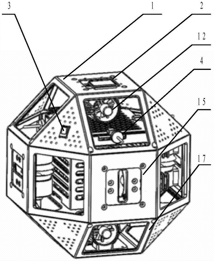
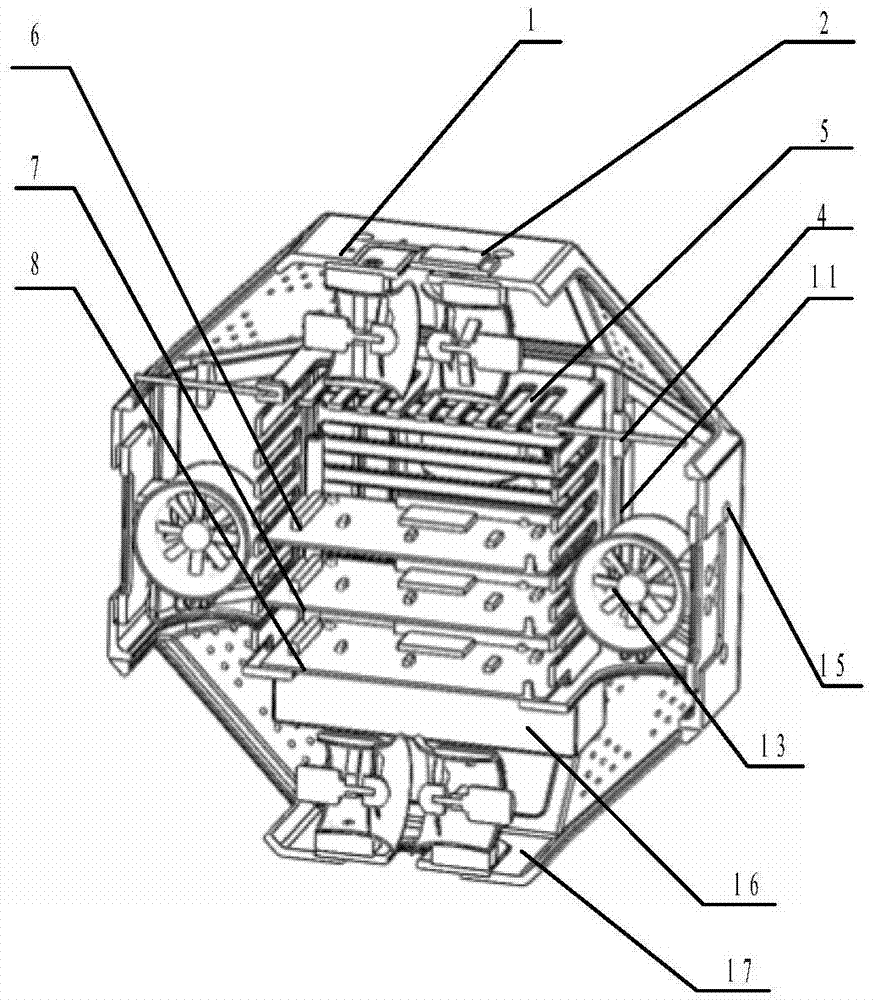
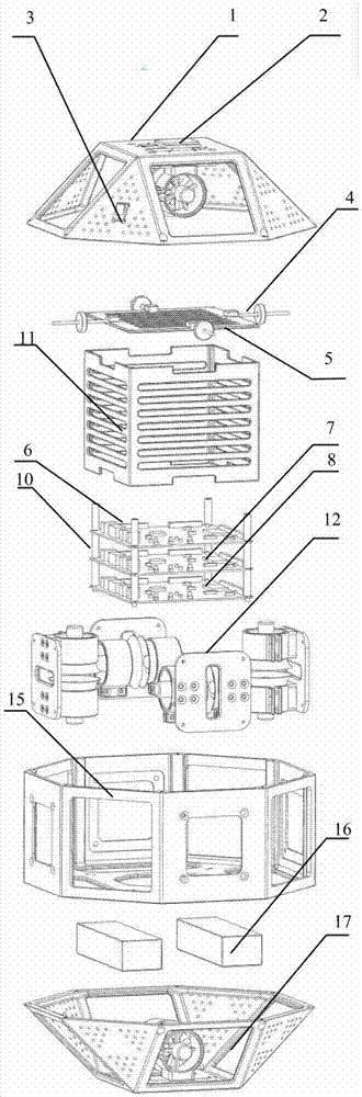
[0029] like Figures 1 to 3 As shown, the present invention includes an upper casing 1, a camera module 2, a switch 3, a balance weight assembly 4, a circuit support frame upper cover 5, a main circuit board 9, a circuit support frame 11, a ducted fan module assembly 12, a middle casing Body 15, battery 16 and lower casing 17, wherein the upper casing 1, the middle casing 15 and the lower casing 17 are connected in sequence to form an octahedral cavity, and the connection between the upper casing 1 and the middle casing 15 and the middle casing The connection between the shell 15 and the lower shell 17 adopts the cooperation of grooves and bosses. The holes provided around the upper and lower ends of the middle shell 15 are equipped with wire screw sleeves. Screws connect the upper casing 1 , the middle casing 15 and the lower casing 17 together. The balance weight assembly 4, the upper cover of the circuit support frame 5, the main circuit board 9, the circuit support frame 11, the ducted fan assembly 12 and the battery 16 are respectively housed in the upper, middle and lower shells 1, 15 and 17. inside the face cavity.
[0030] The upper casing 1 and the lower casing 17 are respectively provided with at least one ducted fan assembly 12. The number of ducted fan assemblies 12 set on the upper casing 1 is the same as the number of ducted fan assemblies 12 set on the lower casing 17. This embodiment For example, the upper casing 1 and the lower casing 17 are respectively provided with a ducted fan assembly 12, which are respectively a ducted fan assembly A12a and a ducted fan assembly B12b.
[0031] like Figures 1 to 3 and Figure 7 As shown, the upper casing 1 includes a top surface and eight sides that are connected in sequence and are respectively connected to the top surface. The ducted fan assembly A12a provided on the upper casing 1 is installed in the positioning groove 19 opened on the lower surface of the top surface. Inside. The eight sides of the upper casing 1 include four triangular faces and four square faces, each triangular face and each square face are arranged at intervals, and the four square faces are all provided with air inlet and outlet 18, that is, there are four air inlets and outlets 18; 3 is installed on any triangular surface of the upper casing 1 and connected to the main circuit board 9 ; a camera module 2 connected to the main circuit board 9 is mounted on the top surface of the upper casing 1 .
[0032] like Figures 1 to 3 and Figure 9 As shown, the lower casing 17 has the same shape as the upper casing 1, including a bottom surface and eight side surfaces that are connected in sequence and are respectively connected to the bottom surface. The ducted fan assembly F12f provided on the lower casing 17 is installed on the bottom surface. in the positioning groove 19 opened on the upper part. The eight sides of the lower casing 17 include four triangular surfaces and four square surfaces, each triangular surface and each square surface are spaced apart, and the four square surfaces are all provided with air inlets and outlets 18 , that is, there are four air inlets and outlets 18 .
[0033] like Figures 1 to 3 and Figure 8As shown, the middle shell 15 includes a bottom surface and eight side surfaces that are sequentially connected and respectively connected to the bottom surface. The lower side and the upper sides of the eight side surfaces of the lower case 17 are connected. The bottom surface of the middle shell 15 is provided with two groups of inner and outer threaded positioning holes with different diameters along the circumferential direction, each group of threaded positioning holes is four, evenly distributed along the circumferential direction, respectively outer circumferential positioning holes and inner circumferential positioning holes. The bottom of the circuit support frame 11 is provided with four threaded positioning holes, which are fixed to the outer peripheral positioning holes on the bottom surface of the middle casing 15 by screws; the inside of the circuit support frame 11 accommodates the main circuit board installed on the bottom surface of the middle casing 15 9. The top of the circuit support frame 11 is provided with a circuit support frame upper cover 5 , and a plurality of balance weight components 4 are evenly distributed on the circuit support frame upper cover 5 . There are ducted fan assemblies 12 mounted on the middle casing 15 in four directions around the periphery of the circuit support frame 11 , and the eight sides of the middle casing 15 are spaced with air inlets and outlets 18 , namely, air inlets and outlets 18 . There are four, and four ducted fan assemblies 12 are respectively installed on the side between the two air inlets and outlets 18 of the middle casing 15, and are respectively ducted fan assembly B12b, ducted fan assembly C12c, ducted fan assembly D12d, ducted fan assembly The four sides of the fan assembly E12e on which the four ducted fan assemblies 12 are installed are provided with positioning grooves 19 for installing the ducted fan assemblies 12 . The batteries 16 (two batteries 16 in this embodiment) are mounted on the lower surface of the bottom surface of the middle case 15 and are connected to the main circuit board 9 .
[0034] like Image 6 As shown, the main circuit board 9 includes a posture module 6, a control module 7 and a power module 8, and the posture module 6, the control module 7 and the power module 8 are connected by a plurality of (four in this embodiment) inter-board support columns 10 , The four inter-board support columns 10 are all copper columns, and the lower ends are threaded, which are respectively screwed to the inner circumference positioning holes of the bottom surface of the middle casing 15 .
[0035] like Figure 5 As shown, four groups of balance weight assemblies 4 are installed on the upper cover 5 of the circuit support frame in this embodiment, and each group of balance weight assemblies includes a threaded guide rod 20 and a mass block 21 with internal threads. The threaded guide rod 20 is installed on the upper cover 5 of the circuit support frame, the mass block 21 is threadedly connected to the threaded guide rod 20, and the position of the center of gravity of the aircraft can be adjusted by adjusting the position of the mass block 21 on the threaded guide rod 20.
[0036] The ducted fan assemblies 12 on the upper casing 1, the middle casing 15 and the lower casing 17 are respectively connected to the main circuit board 9, such as Figure 4 As shown, each ducted fan assembly 12 has the same structure and includes a ducted fan fixing member 14 and two ducted fans 13. The two ducted fans 13 are installed on the ducted fan fixing member 14 opposite to each other, that is, two ducted fans 13 are installed on the ducted fan fixing member 14. The air outlet directions of the ducted fans 13 are opposite. The axial centerlines of the ducted fan assembly A12a on the upper casing 1 and the ducted fan assembly F12f on the lower casing 17 are coplanar, and both are parallel to the horizontal plane; In the ducted fan assembly B12b, the ducted fan assembly C12c, the ducted fan assembly D12d, and the ducted fan assembly E12e, the axial centerlines of the ducted fan assembly B12B and the ducted fan assembly D12d arranged in the front-rear direction are perpendicular to the left-right direction The axial centerlines of the ducted fan assembly C12c and the ducted fan assembly E12E, and the axial centerlines of the ducted fan assembly B12b and the ducted fan assembly D12d arranged in the front and rear directions are parallel to the horizontal plane, and the ducted fans arranged in the left and right directions are parallel to the horizontal plane. The axial centerlines of the assembly C12c and the ducted fan assembly E12e are perpendicular to the horizontal plane, and the axial centerlines of the ducted fan assembly A12a on the upper casing 1 and the ducted fan assembly F12f on the lower casing 17 and the front and rear directions are set. The projections of the axial centerlines of the ducted fan assembly B12b and the ducted fan assembly D12d on the horizontal plane are perpendicular to each other. Alternatively, the axial centerlines of the ducted fan assembly C12c and the ducted fan assembly E12e arranged in the left and right directions are parallel to the horizontal plane, and the axial centerlines of the ducted fan assembly B12B and the ducted fan assembly D12d arranged in the front and rear directions are perpendicular to the horizontal plane, The axial centerlines of the ducted fan assembly A12a on the upper casing 1 and the ducted fan assembly F12f on the lower casing 17 and the axial centerlines of the ducted fan assembly C12c and the ducted fan assembly E12e arranged in the left and right directions are in The projections on the horizontal plane are perpendicular to each other.
[0037] The battery 16 is respectively connected with the attitude module 6, the control module 7 and the power supply module 8. The switch 3, the camera module 2 and the ducted fan assemblies 12 on the upper casing 1, the middle casing 15 and the lower casing 17 are respectively connected to the control unit. The modules 7 are connected to the power modules 8 respectively.
[0038] The working principle of the present invention is:
[0039] The battery 16 supplies power to the main circuit board 9, and the power supply module 8 on the main circuit board 9 supplies power to each device according to the operating voltage of each device; the attitude module 6 monitors the current aircraft attitude information in real time through sensors, and sends the aircraft attitude information to the control module 7. , the control module 7 is used to communicate with the outside world, and at the same time sends out control signals to adjust the speed of each ducted fan assembly 12 to control the aircraft. The image information collected by the camera module 2 is sent to the upper computer via the control module 7 on the main circuit board 9, and the upper computer receives the image information wirelessly and displays and processes it in real time.
[0040] The present invention has six ducted fan assemblies 12 in total, and ducted fan assemblies 12 are installed on the front, rear, left, right, top, and bottom of the octahedral aircraft, and two ducted fans 13 in each direction. When the ducted fan 13 with the ducted fan assembly A12a at the back in the upper casing 1 and the ducted fan 13 with the ducted fan assembly F12f at the back in the lower casing 1 rotate at the same time, the aircraft as a whole moves straight forward; when the upper casing When the ducted fan 13 with the ducted fan assembly A12a in the front of the body 1 and the ducted fan 13 with the ducted fan assembly F12f in the front of the lower casing 1 rotate simultaneously, the whole aircraft moves linearly backwards. When the ducted fan 13 with the ducted fan assembly B12b on the top of the middle casing 15 and the ducted fan 13 with the ducted fan assembly D12d on the top rotate at the same time, the aircraft as a whole moves downward in a straight line; the ducted fan assembly in the middle casing 15 When the ducted fan 13 with B12b at the bottom and the ducted fan 13 with the ducted fan assembly D12d at the bottom rotate at the same time, the aircraft as a whole moves upward in a straight line. When the ducted fan 13 with the ducted fan assembly C12c at the back in the middle casing 15 and the ducted fan 13 with the ducted fan assembly E12e at the back rotate at the same time, the aircraft as a whole moves linearly to the left; the ducted fan assembly in the middle casing 15 When the ducted fan 13 with C12c at the front and the ducted fan 13 with the ducted fan assembly E12e at the front rotate at the same time, the whole aircraft moves in a straight line to the right. When the ducted fan assembly B12b and the ducted fan assembly D12d are arranged oppositely, the two ducted fans 13 in the diagonal direction (that is, the ducted fan 13 with the ducted fan assembly B12b on the top and the ducted fan assembly D12d on the bottom When the ducted fan 13 or the ducted fan 13 with the ducted fan assembly B12b at the bottom and the ducted fan 13 with the ducted fan assembly D12d at the top rotate at the same time, the overall rotation of the aircraft can be realized; The two ducted fans 13 in the ducted fan assembly C12c and the ducted fan assembly E12e in the diagonal direction (that is, the ducted fan 13 in the front of the ducted fan assembly C12c and the ducted fan in the rear of the ducted fan assembly E12e) 13 or when the ducted fan 13 with the ducted fan assembly C12c at the back and the ducted fan 13 with the ducted fan assembly E12e at the front rotate at the same time, the overall rotation of the aircraft can be realized; When the ducted fan 13 with the ducted fan assembly A12a at the back and the ducted fan 13 with the ducted fan assembly F12f at the front in the lower casing 1 rotate at the same time, the overall rotation of the aircraft can be realized; When the ducted fan 13 with the A12a at the front and the ducted fan 13 with the ducted fan assembly F12f at the back in the lower casing 1 rotate simultaneously, the whole aircraft can be rotated. Therefore, through the cooperation of the ducted fan assemblies 12 , linear motions in three directions and rotational motions in three directions of the aircraft in three-dimensional space can be realized.

PUM

no PUM

Description & Claims & Application Information

We can also present the details of the Description, Claims and Application information to help users get a comprehensive understanding of the technical details of the patent, such as background art, summary of invention, brief description of drawings, description of embodiments, and other original content. On the other hand, users can also determine the specific scope of protection of the technology through the list of claims; as well as understand the changes in the life cycle of the technology with the presentation of the patent timeline. Login to view more.

Similar technology patents

Preparation method of CaCu3Ti4O12 ceramic

Owner:NORTHWESTERN POLYTECHNICAL UNIV

Connector locking and electromagnetic unlocking device

ActiveCN101908691Acompact structurereliable unlock
Owner:GUIZHOU SPACE APPLIANCE CO LTD

Classification and recommendation of technical efficacy words

  • Reduce aerodynamic noise
  • compact structure

Elevator safety device

InactiveCN101767737AReduce aerodynamic noise
Owner:TOSHIBA ELEVATOR KK

Low-noise rotary capture absorption type oil-gas separator

PendingCN107023347AReduce aerodynamic noisereduce noise
Owner:合肥恒信动力科技股份有限公司

Conditioning method of gas turbine engine components for aerodynamic noise reduction

ActiveUS20180117720A1reduce aerodynamic noise
Owner:ENVAEROSPACE

Smart home system based on internet of things cloud computing

Owner:中国联合网络通信有限公司物联网研究院

Bionic underwater chelonian robot

InactiveCN101134500ACloselycompact structure
Owner:HARBIN ENG UNIV
Why Eureka
Try Eureka