
Sensing welding device for vacuum glass edge sealing

An induction welding and high-frequency induction welding technology, applied in the field of induction welding equipment, can solve the problems of low heating efficiency, over-burning of thin strip solder edges, inability to achieve penetration heating, etc., to improve heating efficiency, improve working life and The effect of safety features

Inactive Publication Date: 2017-07-07
LUOYANG LANDGLASS TECH CO LTD
View PDF3 Cites 2 Cited by
  • Summary
  • Abstract
  • Description
  • Claims
  • Application Information

AI Technical Summary

Problems solved by technology

Due to the influence of the skin effect and the chemical and physical properties of the internal structure of the thin ribbon solder, it is difficult to make the thin ribbon solder reach the magnetic transition point temperature if the magnetic field parallel to the surface of the ribbon is used for induction heating, and penetration heating cannot be achieved.
For induction heating of thin ribbon solder with a thickness of less than 2mm, the edge of the thin ribbon solder will be overburned due to edge effects, magnetic field line interference or superposition between heating channels
Heating the thin ribbon solder with the magnetic force lines perpendicular to the surface of the ribbon can make the thin ribbon solder with a thickness of less than 2mm reach the magnetic transition point temperature, but the heating efficiency is low

Method used


Image

  • Sensing welding device for vacuum glass edge sealing
  • Sensing welding device for vacuum glass edge sealing
  • Sensing welding device for vacuum glass edge sealing

Examples


Embodiment Construction

[0031] The present invention will be described more fully below using examples. This invention may be embodied in many different forms and should not be construed as limited to the exemplary embodiments set forth herein.

[0032] For ease of description, spatially relative terms such as "upper", "lower", "left", "right", etc. may be used herein to describe the relationship of one element or feature to another element or feature shown in the figures. . It will be understood that the spatial terms are intended to encompass different orientations of the device in use or operation in addition to the orientation depicted in the figures. For example, if the device in the figures is turned over, elements described as "below" other elements or features would then be oriented "above" the other elements or features. Thus, the exemplary term "lower" can encompass both an orientation of above and below. The device may be otherwise oriented (rotated 90 degrees or at other orientations) ...


PUM


Abstract

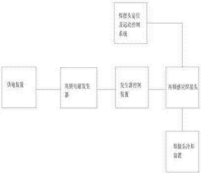
The invention discloses a sensing welding device for vacuum glass edge sealing. The device comprises a power supply device, a high-frequency electromagnetic generator, a generator control device, a high-frequency sensing welding head, a welding head positioning and motion control system, and a welding head cooling device. The power supply device is connected with the high-frequency electromagnetic generator and supplies power to the high-frequency electromagnetic generator; the high-frequency electromagnetic generator is connected with the generator control device and used for generating high-frequency currents; the generator control device is connected with the high-frequency sensing welding head and used for controlling heating parameters of the high-frequency sensing welding head; the high-frequency sensing welding head is connected with the welding head positioning and motion control system and used for welding glass substrates; the welding head positioning and motion control system is used for controlling moving and positioning of the high-frequency sensing welding head; the welding head cooling device is used for cooling the high-frequency sensing welding head. The sensing welding device improves the heating efficiency of high-frequency sensing heating during thin welding strip heating, and automatic sealing of vacuum glass is achieved.

Description

technical field [0001] The invention relates to the technical field of vacuum glass, in particular to induction welding equipment used for edge sealing of vacuum glass. Background technique [0002] At present, the sealing of vacuum glass mainly adopts two forms, one is low glass powder sealing, the other is metal sealing, and low glass powder is used for sealing, which needs to be heated to a higher temperature, generally around 400-600 °C And most of them all need to heat the glass plate as a whole. At this time, if the glass substrate for making vacuum glass is tempered glass, it will cause annealing of the tempered glass. Therefore, the use of low melting point metal materials for sealing has greater advantages for the production of fully tempered vacuum glass. [0003] Solder is preset in the edge area between the upper glass substrate and the lower glass substrate that constitute the vacuum glass, the shape of the solder is thin strip, and the thickness of the thin st...

Claims


Application Information

Patent Timeline
IPC IPC(8): C03C27/08
CPCC03C27/08
Inventor 李彦兵王章生
Owner LUOYANG LANDGLASS TECH CO LTD
Learn More