Hydraulic compaction device and hydraulic compaction machine

A tamping device and hydraulic technology, applied in the direction of road and soil protection, road repair, etc., can solve the problems of piston rod and tamper damage, high replacement frequency and cost, and unfavorable long-term use of hydraulic tamper, so as to reduce maintenance costs. , impact mitigation, small vibration effect

Active Publication Date: 2017-07-07
THE THIRD ENG CO LTD OF THE HIGHWAY ENG BUREAU OF CCCC
View PDF4 Cites 11 Cited by
  • Summary
  • Abstract
  • Description
  • Claims
  • Application Information

AI Technical Summary

Problems solved by technology

[0003]At present, the piston rod and tamper of the existing hydraulic compactor are easy to cause damage, and the replacement frequency and cost are high, which is not conducive to the long-term use of the hydraulic compactor

Method used


Image

  • Hydraulic compaction device and hydraulic compaction machine
  • Hydraulic compaction device and hydraulic compaction machine
  • Hydraulic compaction device and hydraulic compaction machine

Examples


Embodiment 1

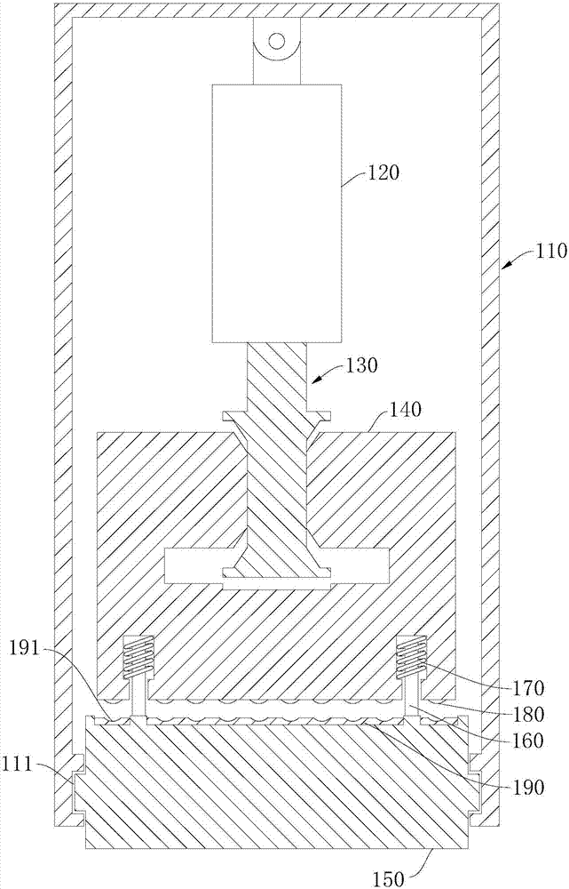
[0034] refer to figure 1 As shown, the embodiment of the present invention provides a hydraulic tamping device, which includes a casing 110 , a hydraulic cylinder 120 , a rammer 140 and a ramming plate 150 .

[0035] In this embodiment, the casing 110 is mainly in the shape of a quadrangular column, and its interior is hollow.

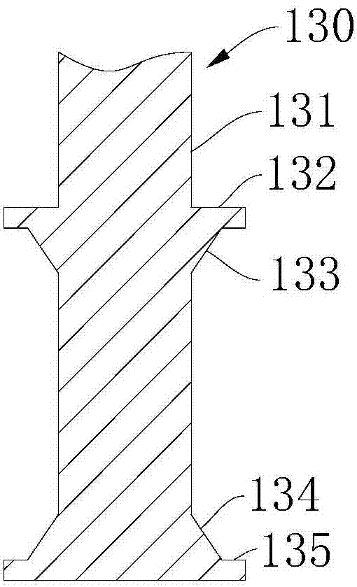
[0036] refer to figure 1 As shown, the hydraulic cylinder 120 is located in the casing 110, and the hydraulic cylinder 120 has a piston rod 130. The end of the hydraulic cylinder 120 away from the piston rod 130 is hinged to the casing 110, and the hinge here can be a hinge.

[0037] Thus, one end of the casing 110 is hinged to the hydraulic cylinder 120 , and the other end of the casing 110 is connected to the tamper plate 150 .

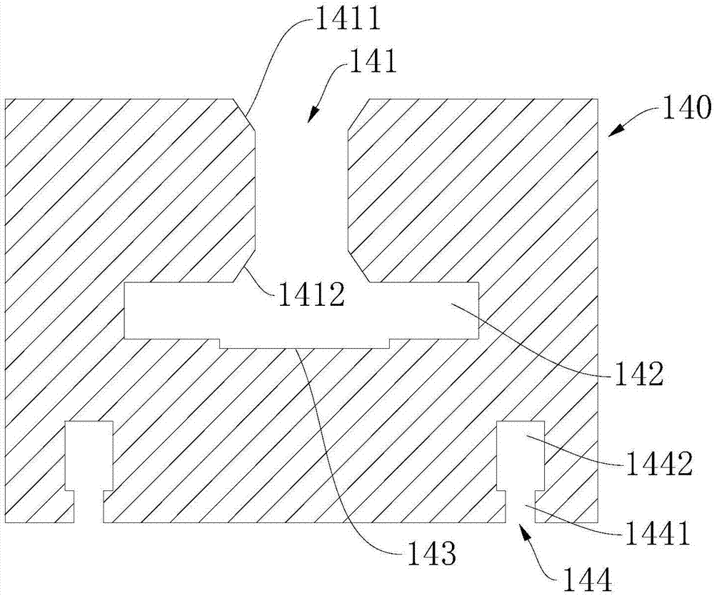
[0038] The rammer 140 is located between the hydraulic cylinder 120 and the rammer 150 , and the rammer 140 is connected to the hydraulic cylinder 120 and the rammer 150 respectively.

[0039] Thus, driven by the hydrauli...

Embodiment 2

[0061] The embodiment of the present invention also provides a hydraulic compaction machine, including a loader, a frame and the above-mentioned hydraulic compaction device, and the loader is connected to the casing 110 of the hydraulic compaction device through the frame.


PUM


Abstract

The invention provides a hydraulic compaction device and a hydraulic compaction machine, and belongs to the field of engineering machinery. The hydraulic compaction device comprises a machine shell, a hydraulic oil cylinder, a compaction rammer and a compaction plate; the hydraulic oil cylinder is located in the machine shell and is hinged to one end of the machine shell, and the compaction plate is fixedly arranged at the other end of the machine shell; the compaction rammer is located between the hydraulic oil cylinder and the compaction plate, a T-shaped groove is formed in the side, close to the hydraulic oil cylinder, of the compaction rammer and comprises a sliding cavity and a limiting cavity which communicate with each other, and the limiting cavity is located in the compaction rammer; and the hydraulic oil cylinder is provided with a piston rod, the piston rod comprises a rod body, a first step part and a second step part, wherein the first step part and the second step part are fixedly connected with the rod body, a part of the rod body extends into the compaction rammer and is in clearance fit with the sliding cavity, the sliding cavity is located between the first step part and the second step part, and the hydraulic oil cylinder is used for driving the compaction rammer to make contact with or get away from the compaction plate. The hydraulic compaction device is reasonable in structure, and the impact force borne by the piston rod and the compaction rammer is effectively relieved.

Description

technical field [0001] The invention relates to the field of engineering machinery, in particular to a hydraulic compacting device and a hydraulic compacting machine. Background technique [0002] The working mode of hydraulic tamping machine can be divided into free falling hammer type and forced falling hammer type. Free falling hammer type (single action): the hydraulic cylinder lifts the hammer body to a set height and releases it, and the hammer body falls freely; after the hammer body falls, it passes The hammer pad hits the assembly of the lower hammer body and the ramming plate, driving the ramming plate to compact the ground. Forced drop hammer type (double action): The hydraulic cylinder raises the hammer body to the set height and then quickly reverses the force, and the hammer body accelerates to fall under the joint action of gravity and hydraulic cylinder thrust; the hammer body falls and hits it through the hammer pad The assembly of the hammer body and the t...

Claims


Application Information

Patent Timeline
Patent Type & Authority Applications(China)
IPC IPC(8): E02D3/046E01C19/34
CPCE01C19/34E02D3/046
Inventor 陈胜亮易达王志刚程英
Owner THE THIRD ENG CO LTD OF THE HIGHWAY ENG BUREAU OF CCCC
Why Eureka
Try Eureka