
Construction method of full-sleeve rotary bored pile with fixed reinforcement cage position

A technology of bored cast-in-place piles and construction methods, applied in sheet pile walls, infrastructure engineering, construction and other directions, can solve the problems of high engineering cost, hanging foot piles, low bearing capacity of piles, etc., and achieves control of pile quality, The effect of speeding up construction progress and improving construction efficiency

Inactive Publication Date: 2019-02-12
SOUTHEAST UNIV
View PDF3 Cites 0 Cited by
  • Summary
  • Abstract
  • Description
  • Claims
  • Application Information

AI Technical Summary

Problems solved by technology

However, in the actual construction, there are also many factors that are not harmonious with the society and the environment, resulting in a series of negative effects such as high project cost, high construction work intensity and long time.
There are two main problems in the traditional cast-in-situ pile construction method: one is that the bearing capacity of the pile is low due to the thick sediment at the bottom of the hole, the floating of the steel cage and the unfixed position, which cannot meet the design strength requirements; It is prone to some quality problems such as broken piles, bottleneck piles, and hanging foot piles
Hidden construction quality problems such as the floating of the steel cage, insufficient verticality of the steel cage, insufficient embedding depth of the steel cage in the concrete, and large deformation of the steel cage due to force in advance have occurred, resulting in some steel bars such as hanging piles and exposed steel bars. Concrete problem piles, which reduce the design strength and durability of the pile body

Method used


Image

  • Construction method of full-sleeve rotary bored pile with fixed reinforcement cage position
  • Construction method of full-sleeve rotary bored pile with fixed reinforcement cage position
  • Construction method of full-sleeve rotary bored pile with fixed reinforcement cage position

Examples


Embodiment Construction

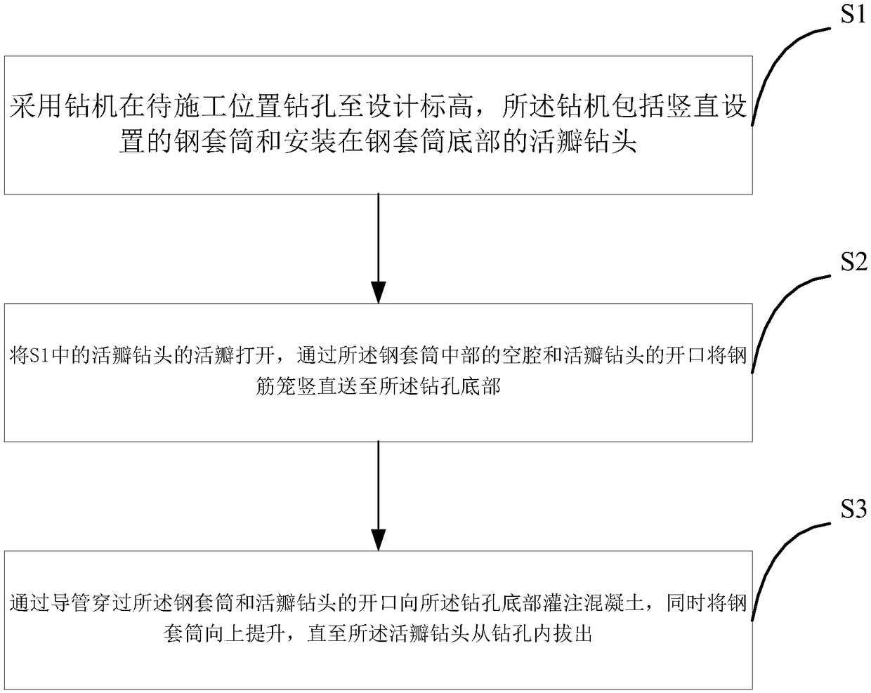
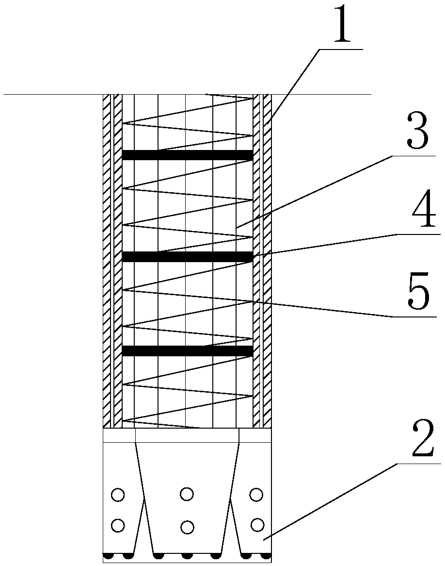
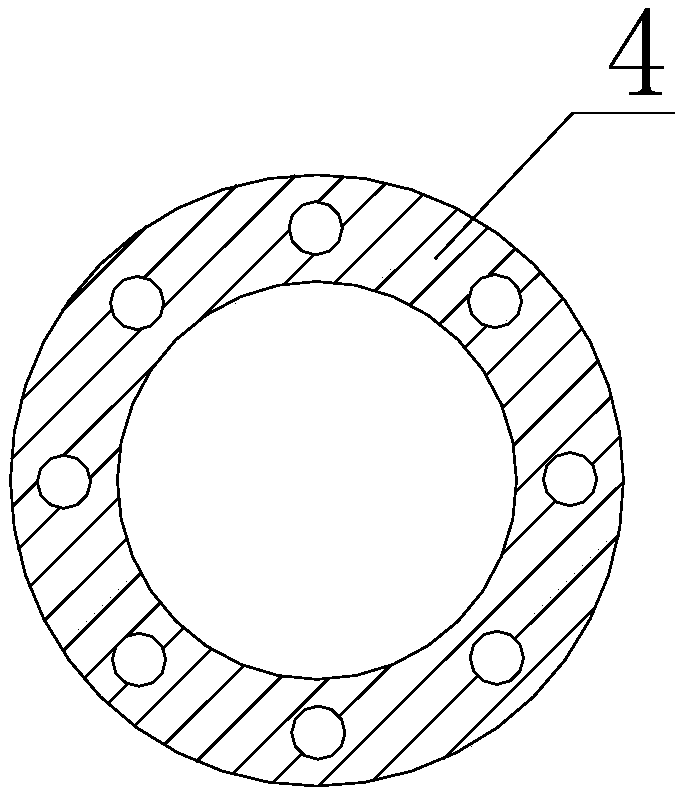
[0023] Such as Figures 1 to 3 as shown, figure 1 It is a flowchart of a construction method for a full-sleeve rotary bored pile with a fixed steel cage position proposed by the present invention, figure 2 It is a structural schematic diagram of the drill bit drilling into the borehole in the construction method of a full-sleeve rotary bored pile construction method with a fixed steel cage position proposed by the present invention, image 3 It is a structural schematic diagram of the steel partition of the reinforcement cage in the construction method of the full-sleeve rotary bored pile with fixed reinforcement cage position proposed by the present invention.

[0024] refer to Figures 1 to 3 A construction method for a full-sleeved rotary bored pile with a fixed steel cage position proposed by the present invention comprises the following steps:

[0025] S1. Use a drilling rig to drill holes to the design elevation at the location to be constructed. The drilling rig inc...


PUM


Abstract

The invention discloses a construction method for a full-sleeve rotary drilling pouring pile with the position of a reinforcing cage being fixed. A drilling machine with a flap drill is adopted to drill a hole to a designed elevation in the position to be constructed; then, the flap drill is opened, and the reinforcing cage is vertically sent to the bottom of the drilled hole through a cavity of the middle of a steel sleeve; and finally, a guide pipe penetrates through the steel sleeve and an opening of the flap drill, concrete is poured into the bottom of the drilled hole, and meanwhile the steel sleeve is lifted up till the flap drill is pulled out from the drilled hole. By means of the optimally-designed construction method for the full-sleeve rotary drilling pouring pile with the position of the reinforcing cage being fixed, the mode of drilling and hole forming is changed based on a full rotary drilling construction technology; drilling stopping is not needed to take soil in the steel sleeve, so that the construction process is accelerated greatly, and pollution of slurry on the peripheral environment of a construction site is lowered; and in the process of lifting the drill, the concrete is poured into the bottom of the drilled hole through the steel sleeve, so that the pile forming quality is controlled significantly, and the construction efficiency of the pouring pile is improved.

Description

technical field [0001] The invention relates to the technical field of road, bridge and building construction, in particular to a construction method for a full-sleeve rotary bored pile with a fixed steel cage position. Background technique [0002] With the rapid development of my country's modernization and the acceleration of urbanization, the construction of viaducts and high-rise buildings has become an important part of my country's large-scale construction and development. The extensive use of cast-in-situ piles can ensure a solid foundation for civil engineering construction, and the related technologies of cast-in-place piles have also been perfected and matured one after another. However, in the actual construction, there are also many factors that are not harmonious with the society and the environment, resulting in a series of negative effects such as high project cost, high construction work intensity and long time. There are two main problems in the traditiona...

Claims


Application Information

Patent Timeline
Patent Type & Authority Patents(China)
IPC IPC(8): E02D5/34
CPCE02D5/34
Inventor 王浩刘发明
Owner SOUTHEAST UNIV
Learn More