Humidifier and atomization enhancement device

A booster device and humidifier technology, which is applied in the field of atomization, can solve the problems of inability to guarantee the fogging effect, high cost of realization, complex structure, etc., and achieve the best market promotion prospects, improved ability, and long diffusion distance.

Active Publication Date: 2017-07-07
BEAR ELECTRICAL APPLIANCE CO LTD
View PDF3 Cites 0 Cited by
  • Summary
  • Abstract
  • Description
  • Claims
  • Application Information

AI Technical Summary

Problems solved by technology

However, there are at least two defects in this technical solution: 1. the wind power of the fan is mainly used to improve the spraying ability of the water mist, and it is necessary to set the air inlet chamber, the air outlet chamber, the fuselage air duct and the fan inside the body of the humidifier. Complicated and costly to implement; ②Especially when the 120° fan shape is set on the mist outlet of the upper cover, the water mist can only be sprayed towards the opening of the mist outlet, which cannot guarantee the best mist output effect

Method used


Image

  • Humidifier and atomization enhancement device
  • Humidifier and atomization enhancement device
  • Humidifier and atomization enhancement device

Examples


no. 1 example

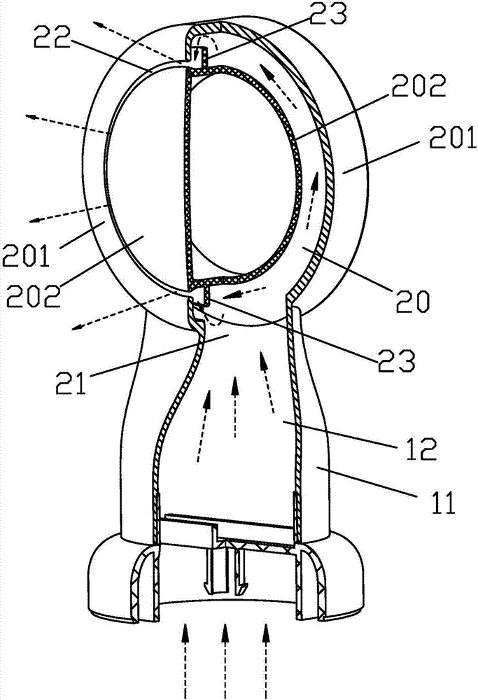
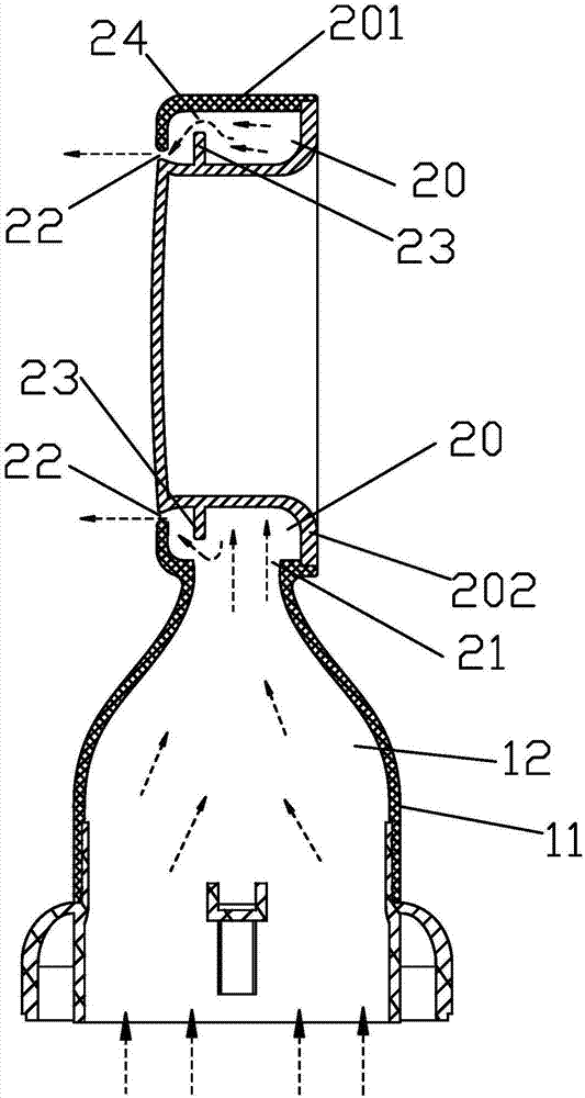
[0022] combine figure 1 and figure 2 as shown ( figure 1 and figure 2 The middle dotted line arrow represents the movement direction of water mist), the atomization enhancement device proposed by the present invention includes: a pressurized chamber 20 with a mist inlet 21 and a mist outlet 22, the mist inlet 21 of the pressurized chamber 20 and the mist outlet Pipe (not shown in the figure) is connected; Used to make the water mist gather in the pressurization chamber 20 to increase the stopper 23 of water mist pressure, this stopper 23 is fixed on the inner wall of the pressurization chamber 20 and is positioned at the water mist from The water mist flow path from the mist inlet 21 to the mist outlet 22, there is a water mist flow port 24 between the stopper 23 and the inner wall of the booster chamber 20, and the water mist after the pressure is increased is accelerated from the water mist flow port 24 Overflow and spray from mist outlet 22.

[0023] Wherein, the pres...

Embodiment 2

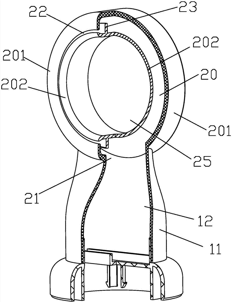
[0028] Considering that the water mist with smaller particles accelerates to be sprayed from the mist outlet 22 under the action of the internal pressure of the pressurized chamber 20, a negative pressure will be formed near the mist outlet 22, which will cause the sprayed water mist to be easily disturbed and affect the flow of the water mist. Diffusion distance and diffusion uniformity. Such as image 3 and Figure 4 As shown, an air duct 25 is set on one side of the pressurized chamber 20, and the negative pressure at the mist outlet 22 is supplemented through the air duct 25, so that the pressure at the mist outlet 22 is balanced, and the water sprayed from the mist outlet 22 is ensured. The fog will not be turbulent, so it can spread farther and more uniformly, further improving the fogging effect.

[0029] in, image 3 and Figure 4 In the shown embodiment, the pressurization chamber 20 is annular, the mist outlet 22 is a narrow and long annular slit, and the air duc...


PUM


Abstract

The invention discloses a humidifier and an atomization enhancement device. The atomization enhancement device comprises a booster cavity (20) with both a mist inlet hole (21) and a mist outlet hole (22), and a stop block (23) used for collecting mist in the booster cavity (20) to increase the mist pressure, wherein the stop block (23) is fixed on the inner wall of the booster cavity (20) and positioned on a mist flowing path through which mist flows from the mist inlet hole (21) to the mist outlet hole (22); and a mist circulation opening (24) communicating with the mist outlet hole (22) is formed between the stop block (23) and the inner wall of the booster cavity (20). The atomization enhancement device ensures more distant and more uniform mist diffusion, so that the atomization (humidification) capability is improved. The atomization enhancement device has the advantages of simple structure, low implementation cost, strong university and the like.

Description

technical field [0001] The invention relates to atomization technology, in particular to an atomization enhancement device for improving mist output capability, and a humidifier with the atomization enhancement device. Background technique [0002] A humidifier is a commonly used household appliance, which atomizes a liquid (such as water, medicine, fragrance) through an atomizer to achieve the purpose of humidification. At present, there are many types of humidifiers, including ultrasonic humidifiers, electric heating humidifiers, evaporative humidifiers, etc., but the mist nozzles of these humidifiers mostly adopt the traditional straight shape. The mist nozzle is easy to block the water, or the water mist condenses behind the mist nozzle and exposes the countertop where the humidifier is placed, which is not conducive to the diffusion of the water mist, resulting in poor humidification effect. [0003] Chinese patent application CN 2013202047855 discloses a humidifying d...

Claims


Application Information

Patent Timeline
Patent Type & Authority Applications(China)
IPC IPC(8): F24F6/12F24F13/00
CPCF24F6/12F24F13/00Y02B30/70
Inventor 李一峰
Owner BEAR ELECTRICAL APPLIANCE CO LTD
Why Eureka
Try Eureka