Gas flow metering method

A metering method and gas flow technology, applied in the direction of measuring flow/mass flow, liquid/fluid solid measurement, measuring devices, etc., can solve problems such as inaccurate flow values, achieve accurate real-time sound velocity c0, and reduce costs

Active Publication Date: 2017-07-07
ZHEJIANG CHINT INSTR & METER
View PDF6 Cites 15 Cited by
  • Summary
  • Abstract
  • Description
  • Claims
  • Application Information

AI Technical Summary

Problems solved by technology

[0005] Therefore, the technical problem to be solved by the present invention is to overcome the inaccurate flow value measured by the method for measuring gas flow of existing products, and provide a method for measuring gas flow with accurate flow value

Method used


Image

  • Gas flow metering method
  • Gas flow metering method
  • Gas flow metering method

Examples


Embodiment 1

[0055] A method for measuring gas flow in this embodiment includes the following steps:

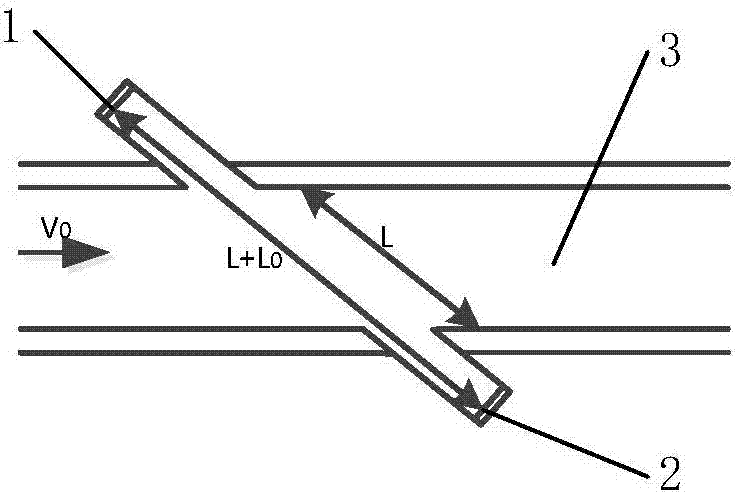
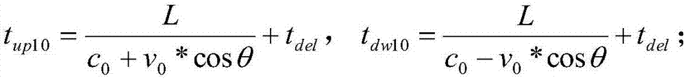
[0056] (S1) The sampling chip controls the first ultrasonic probe 1 so that the first ultrasonic probe 1 sends an ultrasonic signal to the second ultrasonic probe 2, and the sampling chip receives feedback from the second ultrasonic probe 2 according to the first ultrasonic probe 1 To the ultrasonic signal of the second ultrasonic probe 2, the uplink flight time t is obtained up10 ;

[0057] (S2) The sampling chip controls the second ultrasonic probe 2 so that the second ultrasonic probe 2 sends an ultrasonic signal to the first ultrasonic probe 1, and the sampling chip receives feedback from the first ultrasonic probe 1 according to the first ultrasonic probe. Ultrasonic signal from two ultrasonic probes 2 to the first ultrasonic probe 1 to obtain the downlink flight time t dw10 ;

[0058] (S3) according to the hardware delay time to the uplink flight time t up10 and downlink flight ...

Embodiment 2

[0069] The difference between this embodiment and Embodiment 1 is that step (S3), i.e. the measuring method of the gas flow, comprises the following steps:

[0070] (S1) The sampling chip controls the first ultrasonic probe 1 so that the first ultrasonic probe 1 sends an ultrasonic signal to the second ultrasonic probe 2, and the sampling chip receives feedback from the second ultrasonic probe 2 according to the first ultrasonic probe 1 To the ultrasonic signal of the second ultrasonic probe 2, the uplink flight time t is obtained up10 ;

[0071] (S2) The sampling chip controls the second ultrasonic probe 2 so that the second ultrasonic probe 2 sends an ultrasonic signal to the first ultrasonic probe 1, and the sampling chip receives feedback from the first ultrasonic probe 1 according to the first ultrasonic probe. Ultrasonic signal from two ultrasonic probes 2 to the first ultrasonic probe 1 to obtain the downlink flight time t dw10 ;

[0072] (S3) For the obtained downli...

Embodiment 3

[0085] The difference between the present embodiment and the second embodiment also lies in the step (S3), that is, the metering method of the gas flow, which includes the following steps:

[0086] (S1) The sampling chip controls the first ultrasonic probe 1 so that the first ultrasonic probe 1 sends an ultrasonic signal to the second ultrasonic probe 2, and the sampling chip receives feedback from the second ultrasonic probe 2 according to the first ultrasonic probe 1 To the ultrasonic signal of the second ultrasonic probe 2, the uplink flight time t is obtained up10 ;

[0087] (S2) The sampling chip controls the second ultrasonic probe 2 so that the second ultrasonic probe 2 sends an ultrasonic signal to the first ultrasonic probe 1, and the sampling chip receives feedback from the first ultrasonic probe 1 according to the first ultrasonic probe. Ultrasonic signal from two ultrasonic probes 2 to the first ultrasonic probe 1 to obtain the downlink flight time t dw10 ;

[0...


PUM


Abstract

The invention relates to the technical field of metering instruments and concretely relates to a gas flow metering method. The metering method comprises the following steps of controlling a first ultrasonic probe to send an ultrasonic signal to a second ultrasonic probe, receiving an ultrasonic signal based on the first ultrasonic probe to the second ultrasonic probe and fed back by the second ultrasonic probe to achieve upgoing flying time tup10, controlling the second ultrasonic probe to send an ultrasonic signal to the first ultrasonic probe, receiving an ultrasonic signal based on the second ultrasonic probe to the first ultrasonic probe and fed back by the first ultrasonic probe to achieve downgoing flying time tdw10, correcting the upgoing flying time tup10 and the downgoing flying time tdw10 according to hardware delay time, calculating real-time sound speed c0 during the sampling, calculating real-time flow speed v0 according to the real-time sound speed c0, and calculating real-time flow Q0 according to the real-time flow speed v0 and a flow path cross section S. The real-time flow Q0 can be accurately achieved via the calculation method, and further standard gas volume dVc can be accurately achieved by the use of the metering method.

Description

technical field [0001] The invention relates to the technical field of measuring instruments, in particular to a method for measuring gas flow. Background technique [0002] As people pay more and more attention to the environment, gas, as a cleaner and more environmentally friendly energy source, has received more and more attention and application. With the construction and popularization of gas transmission pipelines, gas meters have sprung up like mushrooms. From mechanical to electronic, from membrane to ultrasonic, the continuous emergence of new concepts and new technologies reflects people's pursuit of high quality. And born. In order to adapt to the development needs of the natural gas industry, especially the gas company's demand for natural gas measurement, the natural gas measurement method has received widespread attention from ultrasonic gas meter manufacturers. [0003] At present, in the prior art, such as the Chinese patent document CN106404084A, a method ...

Claims


Application Information

Patent Timeline
Patent Type & Authority Applications(China)
IPC IPC(8): G01F1/66
CPCG01F1/66
Inventor 田舟虞敏杰赵健波
Owner ZHEJIANG CHINT INSTR & METER
Why Eureka
Try Eureka