Clamp-type flange leakage monitoring device
A clamp-type flange and monitoring device technology, which is applied in the direction of measuring devices, fluid tightness testing, machine/structural component testing, etc., can solve harmful problems and achieve the effect of avoiding disasters and high measurement sensitivity
- Summary
- Abstract
- Description
- Claims
- Application Information
AI Technical Summary
Problems solved by technology
Method used
Image

Examples
Embodiment Construction
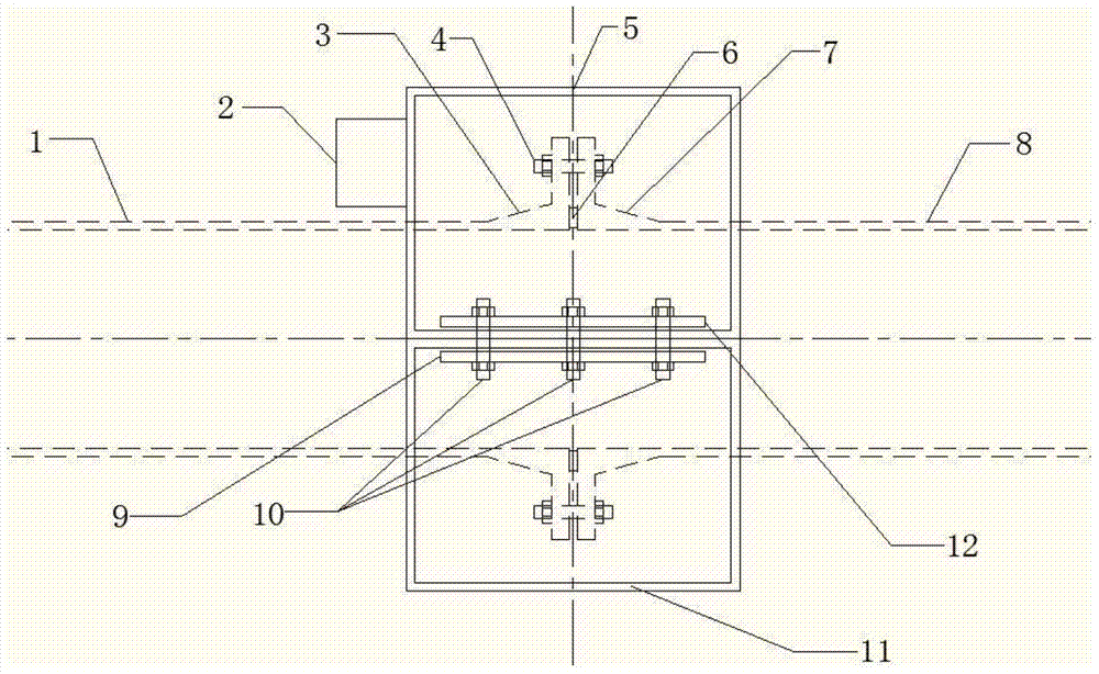
[0014] A clamp type flange leakage monitoring device
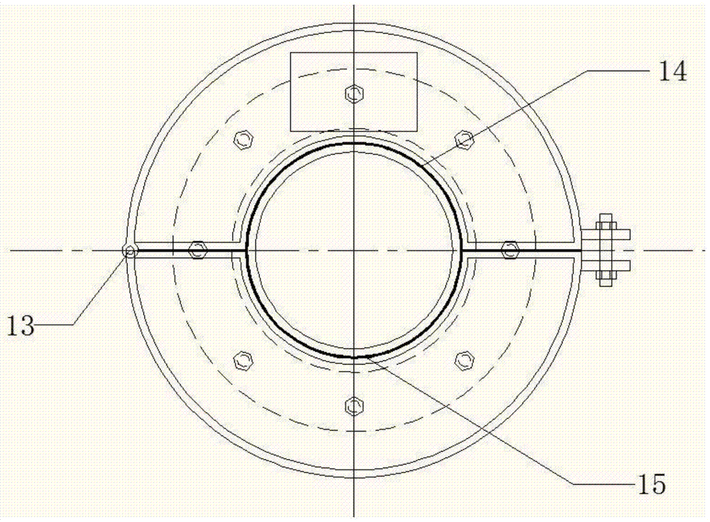
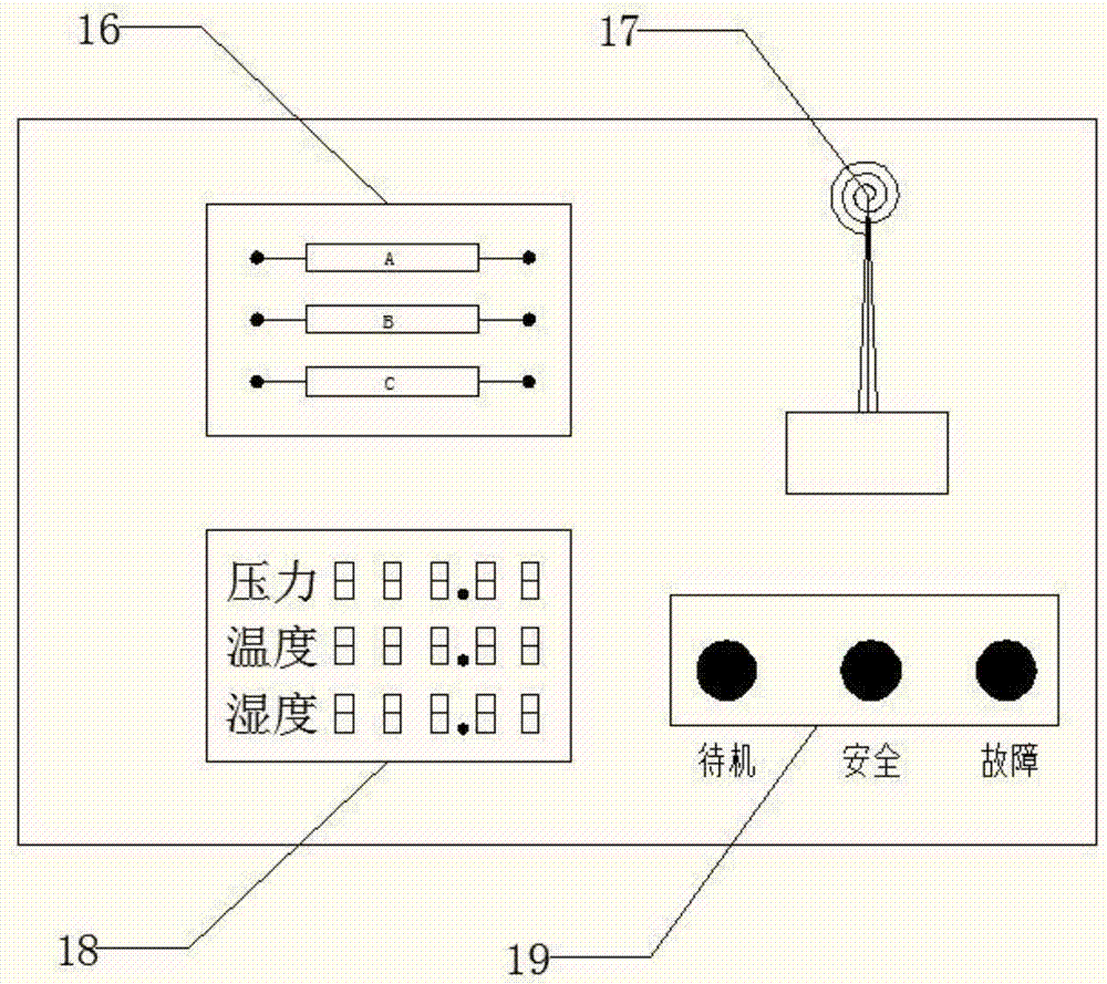
[0015] Such as figure 1 , figure 2 , image 3 As shown: the clamp-type flange leakage monitoring device includes an upper leakage detection cavity 5 and a lower leakage detection cavity 11 . The flange connection system is composed of left pipe 1, left flange 3, gasket 6, right flange 7, right pipe 8, and under the action of fastening bolt 4, a closed connection system is formed for the medium to flow inside it, such as figure 1 Shown in the dotted line. The upper leakage detection cavity 5 and the lower leakage detection cavity 11 are closed on the periphery of the flange connection system to monitor the leakage of the flange. The left side of the upper leak detection cavity 5 is provided with a pin hole, and the side of the lower leak detection cavity 11 corresponding to the upper leak detection cavity 5 is also provided with a pin hole complementary to the upper leak detection cavity 5. The leak detection cavity 5...
PUM
 Abstract
Description
Claims
Application Information
 - Generate Ideas
- Intellectual Property
- Life Sciences
- Materials
- Tech Scout
- Unparalleled Data Quality
- Higher Quality Content
- 60% Fewer Hallucinations
Browse by: Latest US Patents, China's latest patents, Technical Efficacy Thesaurus, Application Domain, Technology Topic, Popular Technical Reports.
© 2025 PatSnap. All rights reserved.Legal|Privacy policy|Modern Slavery Act Transparency Statement|Sitemap|About US| Contact US: help@patsnap.com