Rail welding seam ultrasonic flaw detection device

A flaw detection device and ultrasonic technology, applied in measurement devices, analysis of solids using sonic/ultrasonic/infrasonic waves, and material analysis using sonic/ultrasonic/infrasonic waves, etc. problems, to achieve the effect of reducing work intensity, improving detection efficiency and quality, and comprehensive detection range

Pending Publication Date: 2017-07-07
NANTONG UNION DIGITAL TECH DEV
View PDF15 Cites 5 Cited by
  • Summary
  • Abstract
  • Description
  • Claims
  • Application Information

AI Technical Summary

Problems solved by technology

Since manual flaw detection is greatly affected by human factors such as personnel technical level and sense of responsibility, problems such as missed detection and false alarms often occur, making the quality and efficiency of manual flaw detection low, and due to the shape and structure of the rail, it is difficult to use flaw detection. The car directly conducts a comprehensive inspection of the rail weld from the rail tread, resulting in low quality stability of the rail weld
[0003] In view of the above-mentioned problems of rail weld detection, Chinese patent No. 201420745135.6 discloses "a rail weld flaw detector", which effectively solves the adverse effects of manual operation, but the rail weld flaw detector, The overall size is large, and it is difficult to apply to the on-site inspection of in-service rail welds
In addition, my country's patent No. 201610968932.4 discloses "an ultrasonic detection device and detection method for rail welds". In the actual use of this device, the operator needs to perform manual flaw detection on the rail foot and the triangular area of ​​the rail bottom at the weld, and it is difficult to fully save the inspection data of a single weld

Method used


Image

  • Rail welding seam ultrasonic flaw detection device
  • Rail welding seam ultrasonic flaw detection device
  • Rail welding seam ultrasonic flaw detection device

Examples


Embodiment Construction

[0023] The present invention will be further described in detail below in conjunction with the accompanying drawings and examples. The following examples are explanations of the present invention and the present invention is not limited to the following examples.

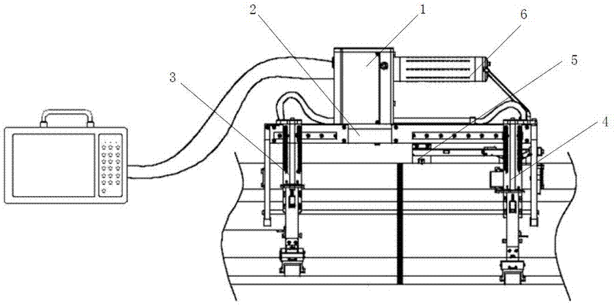
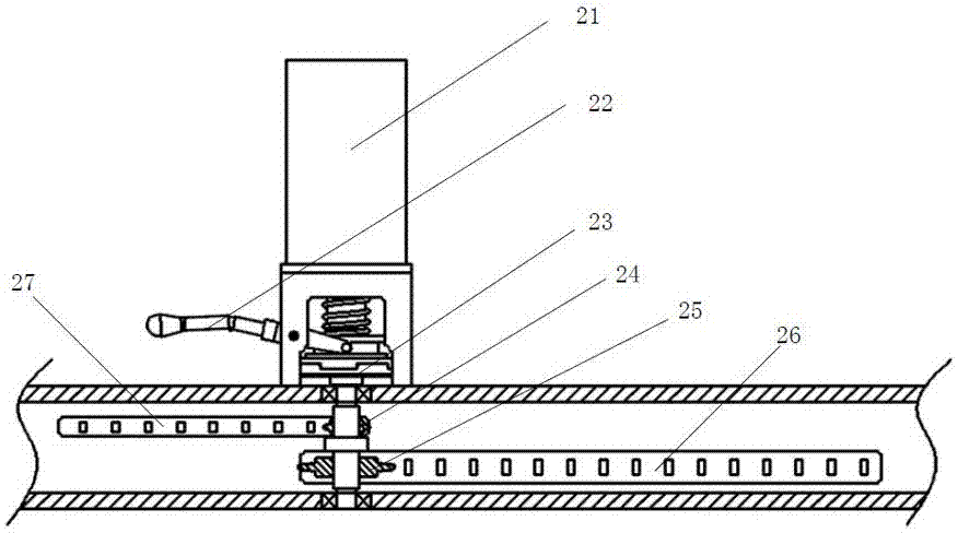
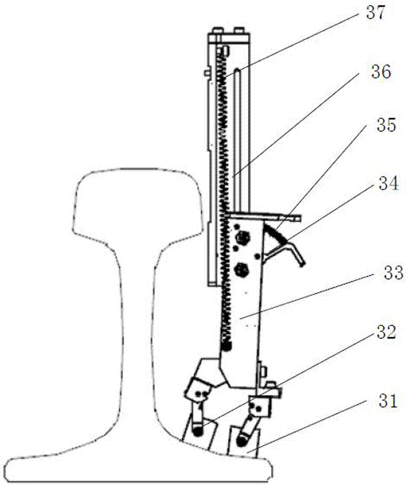
[0024] As shown in the figure, a rail weld ultrasonic flaw detection device of the present invention includes an ultrasonic flaw detector, a drive controller 1, a transmission mechanism 2, a first detection arm 3, a second detection arm 4, a third detection arm 5, a Four detection arms and lifting rods 6, the first detection arm 3 and the second detection arm 4 are arranged on one side of the transmission mechanism 2 and driven by the transmission mechanism 2 to slide in the horizontal direction, the third detection arm 5 and the fourth detection arm are arranged on the transmission mechanism 2 The other side is driven by the transmission mechanism 2 to slide along the horizontal direction. The lifting rod 6 is horiz...


PUM


Abstract

The invention discloses a rail welding seam ultrasonic flaw detection device. The device comprises an ultrasonic flaw detector, a driving controller, a transmission mechanism, a first detection arm, a second detection arm, a third detection arm, a fourth detection arm and a draw bar, the first detection arm and the second detection arm are arranged at one side of the transmission mechanism and are driven by the transmission mechanism to slide in the horizontal direction, the third detection arm and the fourth detection arm are arranged at the other side of the transmission mechanism and are driven by the transmission mechanism to slide in the horizontal direction, the draw bar is horizontally arranged at the side face of the transmission mechanism, the transmission mechanism is connected to the driving controller and is driven by the driving controller, probes in the first detection arm, the second detection arm, the third detection arm and the fourth detection arm are connected to the driving controller, and the driving controller is connected to the ultrasonic flaw detector. The rail welding seam ultrasonic flaw detection device is compact in structural design and convenient to carry, has a more comprehensive detection range, reduces manual detection work strength, and effectively improves the rail welding seam detection efficiency and quality.

Description

technical field [0001] The invention relates to an ultrasonic flaw detection device, in particular to a rail weld seam ultrasonic flaw detection device. Background technique [0002] Seamless rails are the basis for the normal operation of high-speed railways. During the welding process of the rails, there will be poor welding, and stress or fatigue defects will occur during use, causing damage to the rail line and endangering the safety of the train. Ultrasonic detection of defects in rail welds is the most direct and effective measure to ensure that rail welds can meet the needs of train operation. The detection of the existing rail weld seam mainly adopts manual observation of the weld seam, and ultrasonic detection is performed on each position of the rail weld seam manually. Since manual flaw detection is greatly affected by human factors such as personnel technical level and sense of responsibility, problems such as missed detection and false alarms often occur, makin...

Claims


Application Information

Patent Timeline
Patent Type & Authority Applications(China)
IPC IPC(8): G01N29/04G01N29/265
CPCG01N29/04G01N29/265G01N2291/2623G01N2291/2675G01N2291/0234
Inventor 魏小兵范祥祥宋伟王智杰葛文建杜益
Owner NANTONG UNION DIGITAL TECH DEV
Why Eureka
Try Eureka