
A method and device for determining near-surface velocity field

A velocity field and near-surface technology, applied in the field of geophysical exploration, can solve problems such as uneven distribution of first-arrival rays, low accuracy, and inconformity with the characteristics of geological structure changes

Active Publication Date: 2018-11-16
BC P INC CHINA NAT PETROLEUM CORP +1
View PDF5 Cites 0 Cited by
  • Summary
  • Abstract
  • Description
  • Claims
  • Application Information

AI Technical Summary

Problems solved by technology

[0003] However, in the actual construction process of seismic exploration, the distribution of the offset points in the target work area and the distribution of the first arrivals picked up from the seismic data in the target work area may be uneven to a certain extent, which may lead to the network of first arrival travel time tomography. In the grid model, the distribution of the number of first arrival rays passing through each grid is not uniform
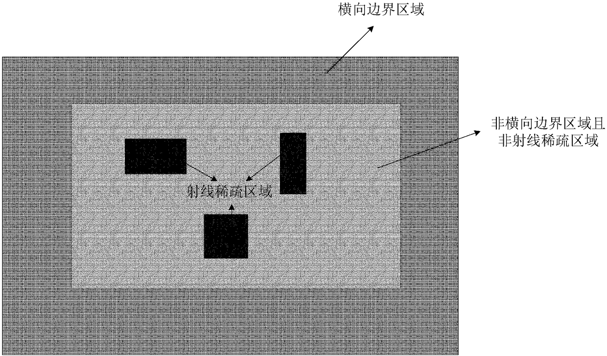
These actual conditions may cause the first arrival rays of more grids in the grid model of first arrival traveltime tomography to not intersect or the first arrival rays are relatively sparse, which may lead to the inversion of first arrival traveltime tomography In the near-surface velocity field based on the grid model, the grid speed in the lateral boundary area, the grid speed in the ray-sparse area, and the grid speed in the vertical boundary area are unreasonable, the accuracy is low, and it does not meet the real situation of the target work area. Characteristics of geological structure changes near the surface
Therefore, the unreasonable speed of the grid in the boundary area and the grid in the ray-sparse area in the grid model needs to be solved urgently

Method used


Image

  • A method and device for determining near-surface velocity field
  • A method and device for determining near-surface velocity field
  • A method and device for determining near-surface velocity field

Examples


Embodiment Construction

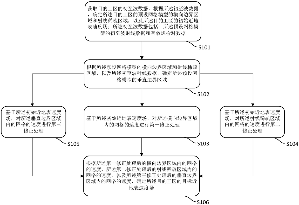
[0094] Embodiments of the present application provide a method and device for determining a near-surface velocity field.

[0095]In order to enable those skilled in the art to better understand the technical solutions in the present application, the technical solutions in the embodiments of the present application will be clearly and completely described below in conjunction with the drawings in the embodiments of the present application. Obviously, the described The embodiments are only some of the embodiments of the present application, but not all of them. Based on the embodiments in this application, all other embodiments obtained by persons of ordinary skill in the art without creative efforts shall fall within the scope of protection of this application.

[0096] figure 1 It is a flow chart of an embodiment of a method for determining the near-surface velocity field in the present application. Such as figure 1 As shown, the method for determining the near-surface velo...


PUM


Abstract

The embodiment of the application discloses a method and apparatus for determining a near-surface velocity field. The method comprises: determining first arrival data of a target work area, a horizontal boundary area and a ray sparse area of a preset mesh model of the target work area, and an initial near-surface velocity field of the target work area; determining a target vertical boundary starting position and a vertical boundary area of the preset mesh model as well as the velocity of a mesh at the target vertical boundary starting position; on the basis of the initial near-surface velocity field, carrying out first correction processing on the velocity of the mesh in the horizontal boundary area, carrying out second correction processing on the velocity of the mesh in the ray sparse area, and carrying out third correction processing on the velocity of the mesh in the vertical boundary area; and according to the velocities of the meshes of the preset mesh model after third-times correction processing, determining a target near-surface velocity field of the target work area. Therefore, accuracy of the velocity of the mesh in the mesh model of the first arrival wave travel time chromatography can be improved.

Description

technical field [0001] The present application relates to the technical field of geophysical prospecting, in particular to a method and device for determining near-surface velocity field. Background technique [0002] In geophysical exploration, first arrival traveltime tomography is one of the main methods to establish the near-surface velocity field. The initial near-surface velocity field used during migration or full-waveform inversion. In the process of first-arrival traveltime tomography, the geological body in the near-surface area of ​​the target work area can be simulated as a three-dimensional grid model. The grid model may include: the direction of the main survey line, the direction of the contact survey line and the vertical direction. These three directions are perpendicular to each other. Among them, the direction of the main survey line and the direction of the contact survey line are parallel to the ground surface, and the vertical direction is perpendicu...

Claims


Application Information

Patent Timeline
Patent Type & Authority Patents(China)
IPC IPC(8): G01V1/30
CPCG01V1/303G01V2210/6222
Inventor 马青坡冯泽元祖云飞肖永新于敏杰
Owner BC P INC CHINA NAT PETROLEUM CORP
Learn More