Light-triggered thyristor device

A silicon device, light trigger technology, applied in semiconductor devices, electrical components, circuits, etc., can solve the problems of poor anti-interference ability, large trigger current, complex process, etc., to achieve high isolation voltage, small trigger current, high photosensitivity Effect

Active Publication Date: 2019-11-22
CRM ICBG (WUXI) CO LTD
View PDF3 Cites 0 Cited by
  • Summary
  • Abstract
  • Description
  • Claims
  • Application Information

AI Technical Summary

Problems solved by technology

[0006] The existing technology adopts the vertical method, which is often complicated in process and high in cost
At the same time, since there is no resistor R, the trigger current is large and the anti-interference ability is poor

Method used


Image

  • Light-triggered thyristor device
  • Light-triggered thyristor device
  • Light-triggered thyristor device

Examples


Embodiment Construction

[0021] In order to describe the technical content of the present invention more clearly, further description will be given below in conjunction with specific embodiments.

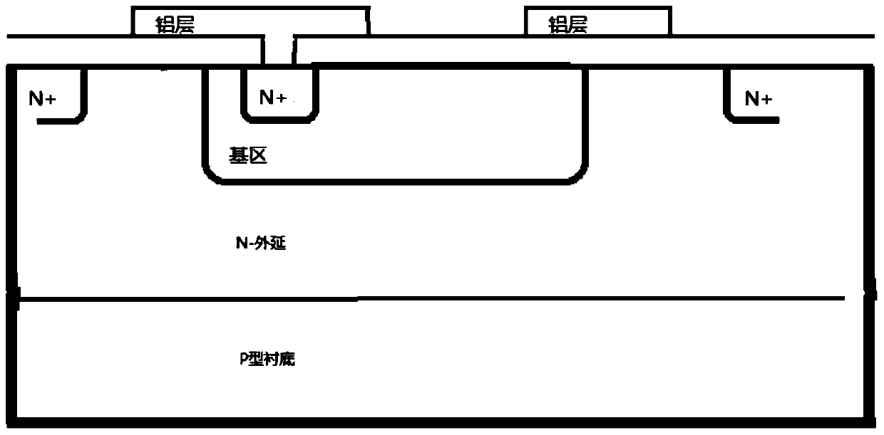
[0022] In the light-triggered thyristor device of the present invention, a P-type diffusion layer is arranged on an N-type substrate, and one N-type diffusion layer is designed to be arranged in one of the P-type diffusion layers. When the infrared light irradiates the P-type diffusion layer, the thyristor is triggered to be turned on. The silicon controlled rectifier of the present invention utilizes the photosensitive trigger of the base area of ​​the NPN tube, has small trigger current, small on-resistance, simple structure, small layout area occupied, and high isolation voltage.

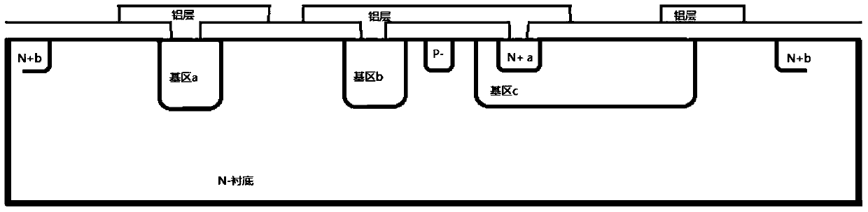
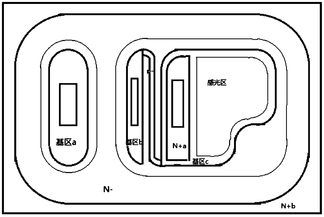
[0023] Such as figure 2 with image 3 As shown, the thyristor structure includes a 4-layer structure, in which the bottom layer is an N-type substrate. The second layer is the base area a, base area b and base area c arran...


PUM


Abstract

The invention relates to a light-triggered silicon controlled rectifier device, which comprises an N type substrate and is characterized in that the N type substrate is provided with a first P type base region, a second P type base region, a third P type base region and a P- type injection region; the second P type base region and the third P type base region are arranged at two sides of the P- type injection region respectively, and the P- type injection region is connected with the second P type base region and the third P type base region; the first P type base region is arranged at the side, which is opposite to the P- type injection region, of the second P type base region; the third P type base region is provided with a first N+ injection region, and the first N+ injection region is located in the third P type base region and close to one side of the P- type injection region; the first N+ injection region is connected with the second P type base region; and a second N+ type injection region is arranged around the N type substrate. The light-triggered silicon controlled rectifier device adopting the structure is small in trigger current, simple in structure, small in layout occupation area, high in isolation voltage and wide in application range.

Description

technical field [0001] The present invention relates to the field of semiconductors, in particular to integrated circuits, in particular to a light-triggered thyristor device. Background technique [0002] In daily applications, it is usually necessary to use low-voltage logic levels to control high-voltage power outputs, and they need to be well isolated. [0003] Since the input and output of the optocoupler are isolated from each other, and the electrical signal transmission has the characteristics of unidirectionality, it has good electrical insulation ability and anti-interference ability. [0004] An optocoupler generally consists of three parts: light emission, light reception, and signal amplification. The input electrical signal drives the light-emitting diode (LED) to emit light of a certain wavelength, which is received by the photodetector to generate a photocurrent, which is further amplified and output. This completes the electrical-optical-electrical convers...

Claims


Application Information

Patent Timeline
Patent Type & Authority Patents(China)
IPC IPC(8): H01L29/747H01L29/06
CPCH01L29/0603H01L29/0684H01L29/747
Inventor 陈继辉程学农荆丹
Owner CRM ICBG (WUXI) CO LTD
Why Eureka
Try Eureka