
Wiring and shaping device of optical projection

A technology of optical projection and projection screen, which is applied in the field of optical projection wiring forming devices and production and production devices, can solve the problem of being unable to adapt to the development needs of paperless and information-based production, easily scratching the insulation sheath of wires, and leaving behind equipment and products. Quality and other issues, to achieve the effect of improving production efficiency and quality, easy to operate, and simple structure

Active Publication Date: 2017-07-07
10TH RES INST OF CETC
View PDF5 Cites 5 Cited by
  • Summary
  • Abstract
  • Description
  • Claims
  • Application Information

AI Technical Summary

Problems solved by technology

The production efficiency of this traditional cable (bundle) production process is low, and there is waste of resources such as paper printing, and the nails used for cable (bundle) positioning and fixing are easy to scratch the outer insulating sheath of the wire, which is easy Leaving quality hidden dangers for equipment products
At the same time, with the continuous promotion and application of concepts such as advanced manufacturing and intelligent manufacturing and related technologies in the manufacturing industry, this traditional cable (bundle) production method cannot adapt to the development needs of paperless, informatized, and digital production. It has become one of the bottlenecks restricting the continuous improvement of the development and production level of electronic equipment

Method used


Image

  • Wiring and shaping device of optical projection
  • Wiring and shaping device of optical projection
  • Wiring and shaping device of optical projection

Examples


Embodiment Construction

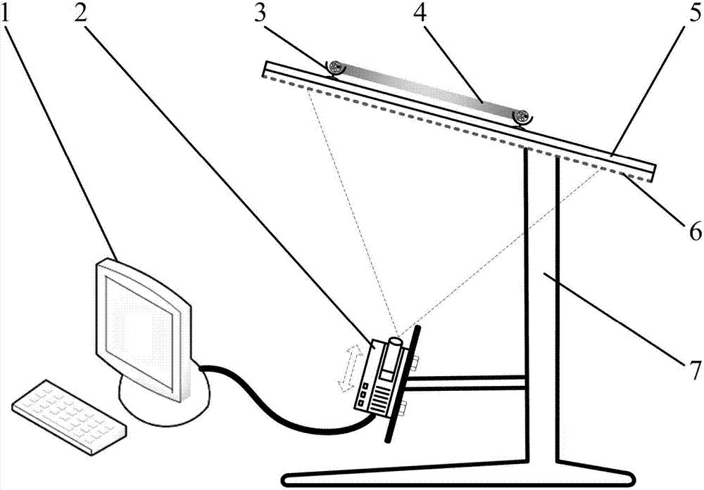
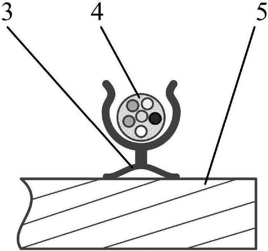
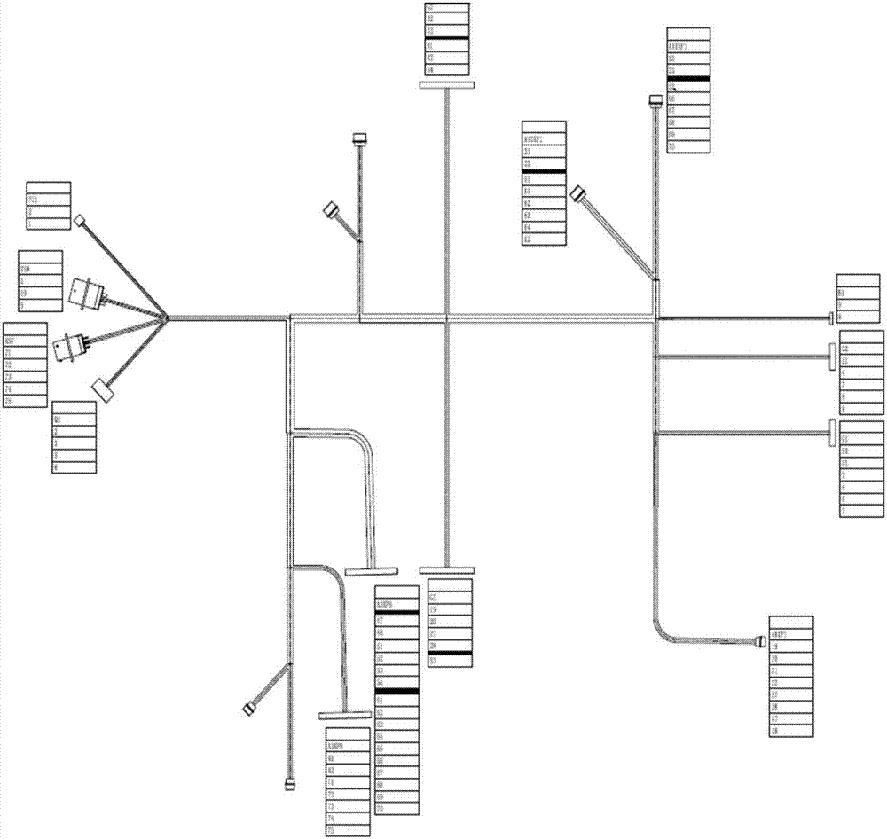
[0015] Refer to figure 1 . In the embodiment described below, the optical projection wiring forming device includes: an optical projector 2, a cable fixing member 3, a transparent wiring forming plate 5, a translucent projection screen 6, and a workbench support 7, characterized by: workbench support 7 is provided with an optical projector 2 under the transparent wiring forming board 5. The optical projector 2 uses the computer 1 to form a nail board diagram with the wiring relationship of the cable bundle 4 and its shape and geometric size information, in a ratio of 1:1 Projected on the translucent projection screen 6, the operator observes the drawings on the translucent projection screen 6 through the transparent wiring forming board 5, and forming the cable bundle 4 on the transparent wiring forming board 5, and the branch of the cable bundle 4 , Turning, etc. are positioned and fixed on the transparent wiring forming board 5 by the cable fixing member 3.

[0016] Preferabl...


PUM


Abstract

The invention discloses a wiring and shaping device of optical projection, and aims at providing the cable wiring and shaping device simple in structural form and easy to operate. A workbench support (7) is provided with an optical projector (2) which is positioned under a transparent wiring and shaping plate (5), the optical projector (2) projects a shaping nail plate drawing which includes a wiring relation and shape geometric size information of a cable harness (4) onto a semi-transparent projection curtain (6) in the proportion of 1:1 via a computer (1), an operation staff observes a drawing on the semi-transparent projection curtain (6) via the transparent wiring and shaping plate (5), shaping of the cable harness (4) is realized in the wiring and shaping plate (5), and branches, turnings and the like of the cable harness (4) are positioned and fixedly shaped on the wiring and shaping plate (5) via cable fixing members (3).

Description

Technical field [0001] The invention relates to the manufacturing field of electronic equipment, and is a device used for the production of cable bundles when the equipment is electrically interconnected and wired, in particular to an optical projection wiring forming device. Background technique [0002] Electrical interconnection technology is defined as the electrical connection between any two discrete contacts is called interconnection, and the electrical connection between two or more points in close proximity is called connection. Generally, electrical interconnection and electrical connection are collectively referred to as "electrical interconnection." In the assembly of electronic products at the component level, printed board level, and complete machine level, any level of assembly is inseparable from interconnection and connection. Assembling and connecting a large number of electronic components, metal or non-metal parts, fasteners and wires of various specification...

Claims


Application Information

Patent Timeline
IPC IPC(8): H01R43/00H01R43/28H04N9/31
CPCH01R43/00H01R43/28H04N9/31H04N9/3141
Inventor 刘潇龙胡国高郑国洪葛长健严宏
Owner 10TH RES INST OF CETC
Learn More