Electronic components typesetting machine

A technology for electronic components and typesetting machines, applied in the direction of electrical components, electrical components, etc., can solve the problems of unable to meet the requirements of automatic typesetting of products, unable to meet the needs of mass production, and low production efficiency.

Active Publication Date: 2022-07-05
广东国灿电子科技有限公司
View PDF4 Cites 0 Cited by
  • Summary
  • Abstract
  • Description
  • Claims
  • Application Information

AI Technical Summary

Problems solved by technology

The current automatic typesetting equipment cannot meet the above-mentioned automatic typesetting requirements for products. Although it is feasible to use manual mold typesetting, the production efficiency is low and cannot meet the needs of mass production.

Method used


Image

  • Electronic components typesetting machine
  • Electronic components typesetting machine
  • Electronic components typesetting machine

Examples


Embodiment Construction

[0025] In order to describe in detail the technical content, structural features, and achieved effects of the present invention, detailed descriptions are given below with reference to the embodiments and the accompanying drawings.

[0026] see Figure 5 , in a specific embodiment of the present invention, an electronic component typesetting machine is used to typeset the capacitor core 900, the capacitor core 900 has a main body 901 and two pins 902 extending from one end of the main body 901, and the electronic component typeset The machine places the pins 902 of several capacitor cores 900 on the strip B in turn and covers them with paper tape P at the same time to glue the pins 902 on the strip B; The other end is uneven.

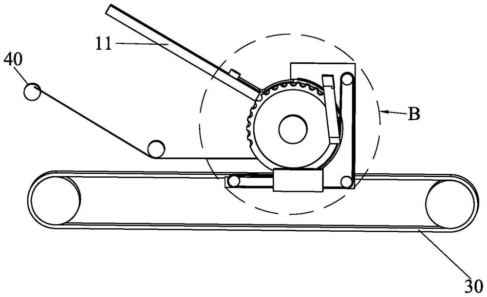
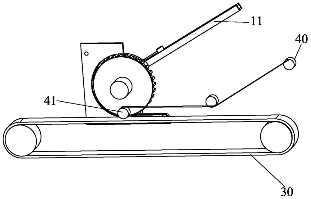
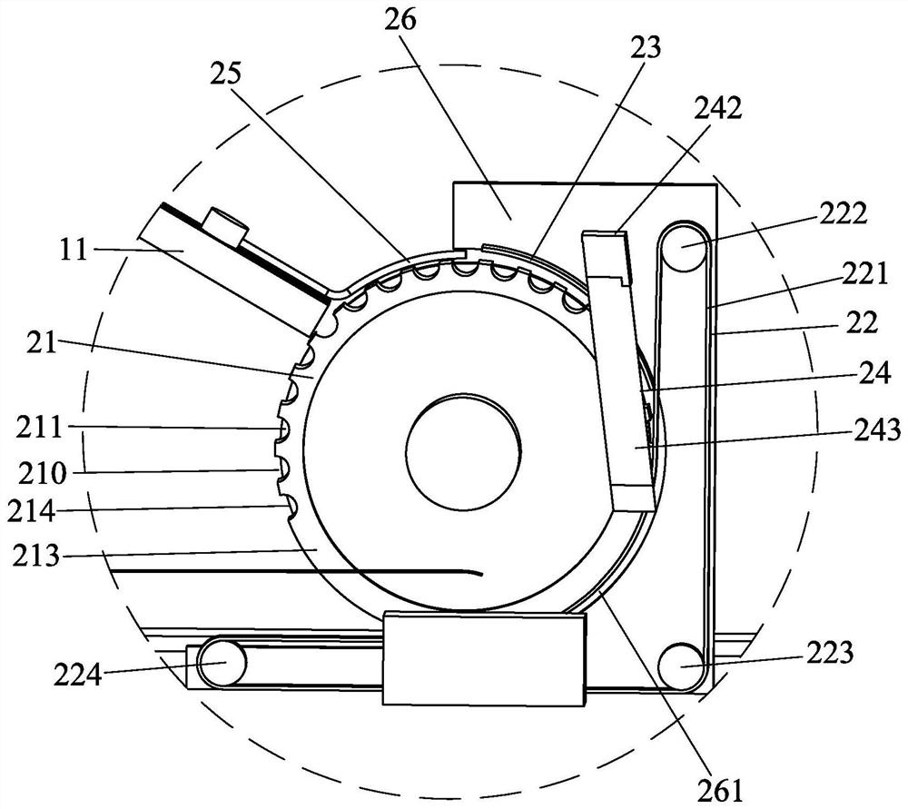
[0027] see Figure 1 to Figure 4 , the electronic component typesetting machine includes a component feeding device, a component conveying device, a strip conveying device 30, a paper tape conveying device 40 and a control drive module (not shown), an...


PUM


Abstract

The invention discloses an electronic component typesetting machine, comprising a component feeding device, a component conveying device, a strip conveying device, and a paper tape conveying device. The component conveying device includes a turntable and a belt conveying structure. The component feeding device feeds several bodies into several positioning slots in sequence, the corresponding pins extend beyond one side of the turntable in the axial direction, and the belt part of the belt conveying structure is adjacent to the side of the turntable. The outer periphery is arranged to compress the corresponding bodies transferred, and the belt is released from the pressing of the corresponding bodies at the bottom end of the turntable; the strip conveyor is horizontally arranged adjacent to the bottom end of the turntable, and the strip conveyor The slats are sequentially conveyed by passing through the corresponding turntable, and when the corresponding electronic components are ready to be separated from the positioning groove, the corresponding pins fall on the corresponding positions of the slats; the paper tape conveying device has a bottom end corresponding to the turntable and a The platen conveying device is provided with a pinch roller.

Description

technical field [0001] The invention relates to the field of typesetting of electronic components, in particular to a typesetting machine for electronic components. Background technique [0002] At present, the capacitor core of an inductive foil film capacitor has a special shape, and the height of the product body is 2-3 times higher than that of the current general-purpose inductive foil film capacitor. The cross-section of the capacitor core is required to be elliptical (the core cannot be flattened or flattened), and the dimensions of the long axis and the short axis are required to be precise. During the typesetting process, the capacitor cannot be caused by mechanical collision or extrusion. Product deformation. The current automatic typesetting equipment cannot meet the above-mentioned requirements for automatic typesetting of products, and although it is feasible to use manual mold typesetting, the production efficiency is low and cannot meet the needs of mass prod...

Claims


Application Information

Patent Timeline
Patent Type & Authority Patents(China)
IPC IPC(8): H05K13/02
CPCH05K13/02H05K13/022
Inventor 刘竞泽刘海平
Owner 广东国灿电子科技有限公司
Why Eureka
Try Eureka