Spiral lifting device for building construction

A technology of spiral lifting and building construction, applied in the direction of lifting devices, lifting frames, etc., can solve the problems of unsatisfactory start-stop control accuracy, screw rod damage, tilting, etc., and achieve the effects of long service life, bending of protection, and convenient use

Inactive Publication Date: 2017-07-11
CHENGDU LYUDI TECH
View PDF0 Cites 4 Cited by
  • Summary
  • Abstract
  • Description
  • Claims
  • Application Information

AI Technical Summary

Problems solved by technology

However, the start-stop control accuracy of the existing screw elevator is not ideal. When the construction object being lifted is heavy and bulky, the screw elevator will tilt, which will easily cause damage to the screw rod.

Method used


Image

  • Spiral lifting device for building construction
  • Spiral lifting device for building construction

Examples


Embodiment Construction

[0013] In order to make the above objects, features and advantages of the present invention more comprehensible, specific implementations of the present invention will be described in detail below in conjunction with the accompanying drawings. In the following description, numerous specific details are set forth in order to provide a thorough understanding of the present invention. However, the present invention can be implemented in many other ways different from those described here, and those skilled in the art can make similar improvements without departing from the connotation of the present invention, so the present invention is not limited by the specific embodiments disclosed below.

[0014] It should be noted that when an element is referred to as being “fixed on” or “disposed on” another element, it may be directly on the other element or there may be an intervening element. When an element is referred to as being "connected to" another element, it can be directly co...


PUM


Abstract

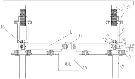
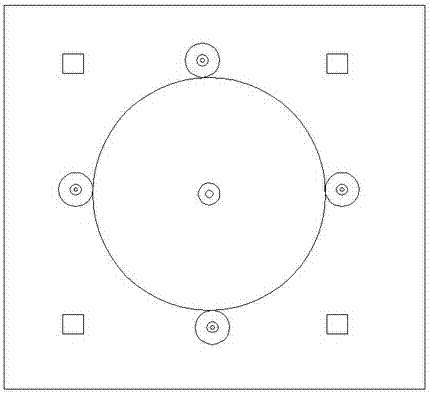
The invention relates to a spiral lifting device for building construction, which includes a workbench, a column, a lower base plate, and a secondary transmission device. It includes a motor, a large gear, a small gear, a base, a shaft, a transmission rod, an externally threaded rod, and an internally threaded rod. The motor is arranged on the upper part of the lower bottom plate and connected by bolts. The large gear and the motor are connected by a large flat key. The base is arranged on the top of the lower bottom plate and Connected by bolts, the shaft is set in the inner hole of the pinion and connected by a flat key, the pinion is set on the upper end of the base and connected by a bearing, the transmission rod is set at the lower end of the internal threaded rod and connected by bolts, and the external threaded rod is set The periphery of the internal threaded rod is connected by threads. The invention has the advantages of reasonable structure, convenient use, good stability, high precision of start-stop control, no skewing, large bearing capacity and long service life.

Description

technical field [0001] The invention relates to the field of building construction, in particular to a spiral lifting device for building construction. Background technique [0002] The screw jack is composed of worm gear, box, bearing, screw and other components. The working principle is: the motor or manual drives the worm to rotate, the worm drives the worm gear to decelerate and rotate, the inner cavity of the worm gear is processed into an internal thread, and the driving screw moves up and down to achieve the effect of lifting. The screw jack is mainly used in the adjustment structure of mechanical lifting action, and is widely used in the field of construction. However, the start-stop control accuracy of the existing screw jack is not ideal. When the construction object to be lifted is heavy and bulky, the screw jack will be inclined, which is easy to cause damage to the screw rod. Contents of the invention [0003] The technical problem to be solved by the presen...

Claims


Application Information

Patent Timeline
Patent Type & Authority Applications(China)
IPC IPC(8): B66F7/06B66F7/28
CPCB66F7/0608B66F7/28
Inventor 梁枫
Owner CHENGDU LYUDI TECH
Why Eureka
Try Eureka