Suction anchor rod device

A rod device and suction anchor technology, which is applied in construction, excavation, and foundation structure engineering, can solve the problems of increased safety risks, small total resistance, and high water content, so as to improve stability and safety, and improve anchor bolt side Frictional resistance, the effect of increasing the side frictional resistance of the bolt

Active Publication Date: 2017-07-11
ZHEJIANG UNIV OF TECH
View PDF4 Cites 8 Cited by
  • Summary
  • Abstract
  • Description
  • Claims
  • Application Information

AI Technical Summary

Problems solved by technology

However, when the geological conditions are poor, such as saturated soft clay, its water content is high, its strength is low, and its friction coefficient is small, so the total resistance provided is often small, while the traditional way to increase the total anchor bolt by increasing the end area Resistance measures have the disadvantages of low efficiency and high cost
Especially in the case of emergency engineering, it often cannot meet the requirements of fast and efficient, increasing safety risks
At the same time, the traditional method of increasing the contact area at the end to increase the bearing capacity of the anchor makes the structure of the anchor more complicated and brings great inconvenience to the construction.

Method used


Image

  • Suction anchor rod device
  • Suction anchor rod device

Examples


Embodiment Construction

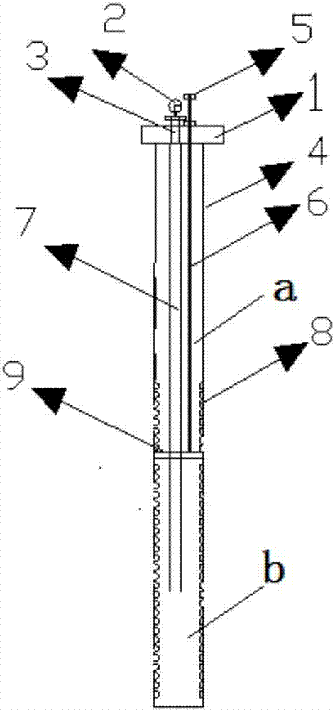
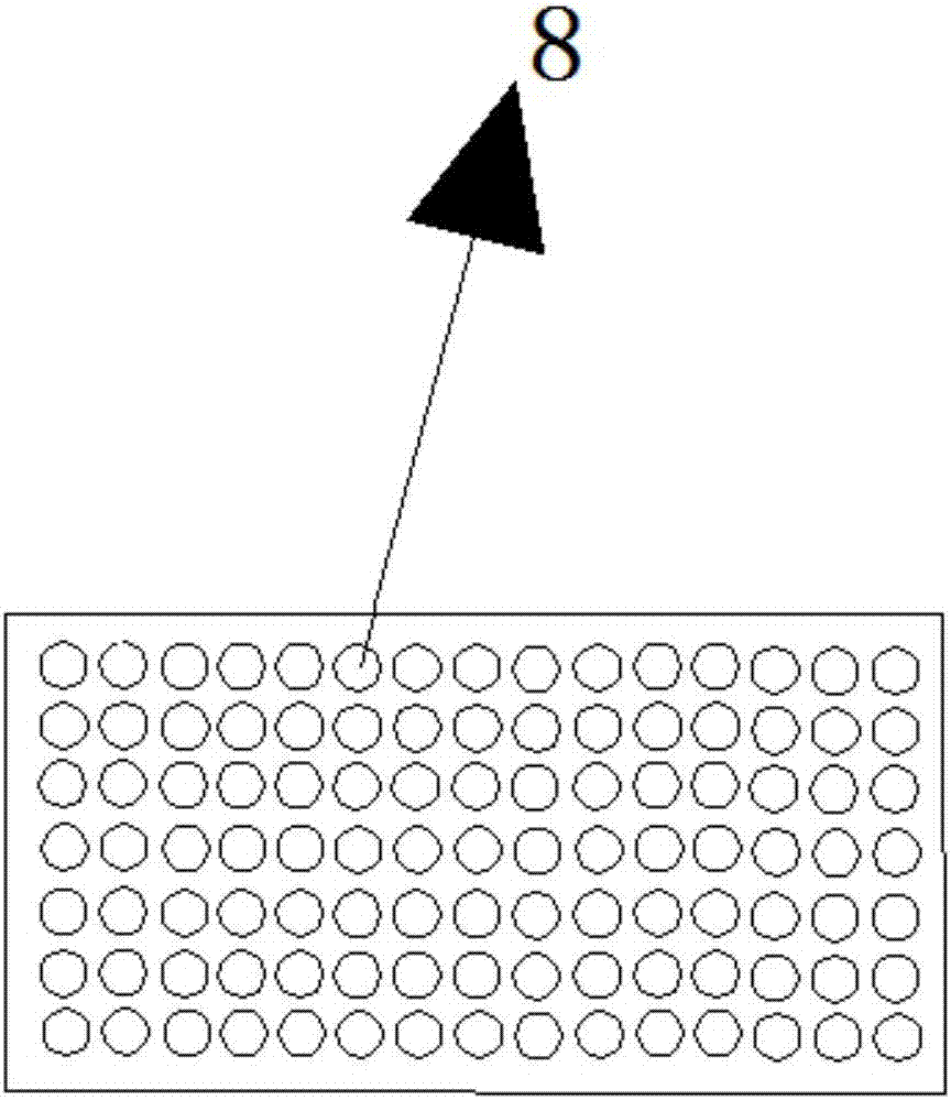
[0019] Referring to the accompanying drawings, a suction anchor device includes a hollow columnar anchor 4, the bottom of the anchor 4 is sealed, and the top of the anchor 4 is equipped with a sealing cover 1, and the sealing cover 1 and The anchor rod 4 is detachably connected; the section of the anchor rod 4 close to the bottom opening is defined as the bottom section, the end close to the top opening is the top section, and several sieve holes 8 are distributed on the side wall of the bottom section of the anchor pole 4, The screen hole 8 communicates with the inner cavity of the anchor rod 4; the anchor rod 4 is provided with a lifting plate 9, and the lifting plate 9 can move up and down along the axial direction of the anchor rod 4 through a lifting device and is arranged on the anchor rod 4. Inside, and the lifting plate 9 divides the inner cavity of the anchor rod 4 into an upper cavity a and a lower cavity b, and defines the upper cavity a that includes the top opening...


PUM


Abstract

A suction anchor rod device comprises a hollow columnar anchor rod. A bottom opening of the anchor rod is sealed, a top opening of the anchor rod is provided with a sealing cover plate, and the sealing cover plate and the anchor rod are detachably connected. The section, close to the bottom opening, of the anchor rod is defined as a bottom section, the section, close to the top opening, of the anchor rod is defined as a top section, a plurality of sieve holes are distributed in the side wall of the bottom section of the anchor rod, and the sieve holes communicate with an inner cavity of the anchor rod. A lifting disk is arranged in the anchor rod, the lifting disk is arranged in the anchor rod in the manner that the lifting disk can move up and down in the axial direction of the anchor rod through a lifting device, the lifting disk divides the inner cavity of the anchor rod into an upper cavity and a lower cavity, the cavity containing the top opening is defined as the upper cavity, and the cavity containing the bottom opening is defined as the lower cavity. The suction anchor rod device further comprises a pressure testing device used for testing the air pressure in the lower cavity and a pressure adjusting device used for adjusting the air pressure in the lower cavity. The suction anchor rod device utilizes the principle of effective stress, under the situation that the total stress is certain, the effective stress is improved by reducing the excess pore pressure, the anchor rod side friction is increased, and the overall stability and safety are improved.

Description

technical field [0001] The invention relates to a suction bolt device. Background technique [0002] Anchor rods are widely used in slope, foundation pit support, foundation pit anti-uplift or building anti-floating and other projects. The main principle is to balance the sliding force or buoyancy of the soil by the resistance provided by the side wall and end of the anchor rod. , so that the whole remains safe and stable. Therefore, the anchor rod is usually embedded in the soil layer with good geological conditions. However, when the geological conditions are poor, such as saturated soft clay, its water content is high, its strength is low, and its friction coefficient is small, so the total resistance provided is often small, while the traditional way to increase the total anchor bolt by increasing the end area Resistance measures have the defects of low efficiency and high cost. Especially in the case of emergency engineering, it often cannot meet the requirements of ...

Claims


Application Information

Patent Timeline
Patent Type & Authority Applications(China)
IPC IPC(8): E02D5/74E02D17/20
CPCE02D5/74E02D17/20
Inventor 胡敏云陈小雨张勇肖斌周培娇潘丽东
Owner ZHEJIANG UNIV OF TECH
Why Eureka
Try Eureka