Multi-section type variable cross-section dynamic compaction method

A technology of variable cross-section and dynamic ramming, which is applied in the fields of soil protection, construction, and infrastructure engineering, etc., can solve the problems of large subsidence, shallow effective reinforcement thickness, and poor reinforcement effect of weak foundation soil, etc., reaching the settlement value The effect of reducing the difference value of settlement and settlement, widening the applicable conditions and scope, and good co-action characteristics

Inactive Publication Date: 2011-11-23
谢开生
View PDF4 Cites 5 Cited by
  • Summary
  • Abstract
  • Description
  • Claims
  • Application Information

AI Technical Summary

Problems solved by technology

After the local foundation soil is stressed, it is easy to have a large amount of subsidence or uneven subsidence between the ramming point and the soil between the ramming points, which will cause the superstructure (structure) to affect the structural safety of the building due to large or uneven subsidence.
Moreover, factors such as the lifting performance of the dynamic ramming machine used in the existing dynamic ramming method and the absorption of the ramming hammer by the rammed pit soil limit the infinite increase of the single-click ramming energy to a certain extent, resulting in weak foundation soil layers. The reinforcement effect in the middle and lower part is poor, and the effective reinforcement thickness is shallow, resulting in a thicker and weak underlying layer in the basement

Method used


Image

  • Multi-section type variable cross-section dynamic compaction method
  • Multi-section type variable cross-section dynamic compaction method
  • Multi-section type variable cross-section dynamic compaction method

Examples


Embodiment 1

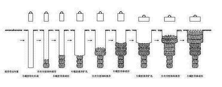
[0036] The inventive method comprises the following steps:

[0037] (1) Clean up and level the construction site

[0038] (2) Dynamic tamping construction of the first tamping body with small cross-section

[0039] ① Measuring and setting of dynamic compaction points: Arrange dynamic compaction points on the construction site according to the design requirements.

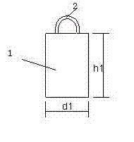
[0040] ② Formation of the ramming pit: the dynamic ramming machine is in place, and the type I rammer (ratio of hammer height h1 to hammer diameter d1 is 1.5, hammer diameter d1=1.2m, static ground pressure value of hammer bottom is 140kPa) is placed at the ramming point, Lift the type I rammer to a set height of 13.0 m, automatically unhook it and drop it to ram the soil, and repeat the ramming to form a ramming pit. When the depth of the designed ramming pit is ≤50cm, backfill the ramming pit with 1.5m thick backfill material and continue to ram until the bottom of the ramming pit is compacted by tamping.

...

Embodiment 2

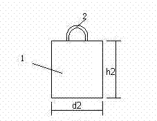
[0060] The rammers and construction techniques used in the multi-stage variable section dynamic compaction method in Example 2 are the same as those in Example 1.

[0061] The difference is that when the thickness of the weak foundation soil layer is less than 9 m, the lower part of the foundation soil layer shall be constructed with a small cross-section or directly with a medium cross-section to make the filling layer or the lower part of the weak foundation soil layer compacted by dynamic compaction, and then The large cross-section construction is adopted to achieve the reinforcement effect of the upper soil layer, so that the upper and lower sections are constructed into a variable cross-section dynamic ramming body or a replacement pier with an inverted convex shape.

[0062] Full ramming construction: After the overall construction of the multi-stage variable cross-section dynamic ramming body in the dynamic ramming area, the entire dynamic ramming area uses Type III ram...

Embodiment 3

[0064] The construction technology used in the multi-stage variable section dynamic compaction method of embodiment 3 is the same as that of embodiment 1.

[0065] The difference is that: for the weak foundation soil layer with a layer thickness of 15-25 m, the first section of the rammed body of the small cross-section is firstly rammed for the deep soil mass of the weak foundation soil layer, and then the middle part of the weak foundation soil layer is Divided into n-2 sections, use rammers with increasing cross-sections from bottom to top to carry out n-2-section variable-section segmental ramming construction, and finally carry out large-cross-section n-section ramming on the soft foundation soil layer soil The dynamic tamping construction is thus constructed into n (n=4 or 5 or 6) sections of multi-section variable cross-section dynamic tamping ramming body or replacement pier body.

[0066] Full ramming construction: After the overall construction of the multi-stage var...


PUM


Abstract

The invention discloses a multi-section type variable cross-section dynamic compaction method, which is the method for treatment of a building foundation, clearing and leveling are firstly performed on a soft foundation space, and multi-section type variable cross-section dynamic compaction construction is further performed on dynamic compaction tamping points which are arranged according to the construction process flow and the technical specifications. During the process of forming a tamping pit and forming tamping bodies, more than two rams in cross sections which are increased gradually are adopted for ramming a soil body of a soft foundation from bottom to top respectively for forming the tamping pit or an expanded hole, dry soil or aggregate is further backfilled into the tamping pit and rammed, tamping of the tamping pit and the backfilled materials is completed section by section, then more than two sections of the dynamic compaction tamping bodies or replacement pier bodies in the cross sections which are gradually increased are formed from the bottom to the top and full compaction operation in a dynamic compaction region is finally performed. After the method is adopted for dynamic compaction and reinforcement, the overall compactness, the strength of the foundation and the bearing capacity are greatly improved, and the foundation is uniform at the upper part and the lower part. The stress stability, the uniformity and the overall rigidity of the foundation soil are significantly increased. The construction quality is more stable, the compression modulus of the foundation is high, and the settlement value and the settlement difference value are obviously reduced.

Description

technical field [0001] The invention relates to a construction method of building foundation treatment technology, which is mainly aimed at the multi-stage variable cross-section dynamic ramming method construction of weak foundation dynamic ramming reinforcement. Background technique [0002] Among the building foundation treatment technologies, the dynamic compaction method has been rapidly popularized and applied throughout the country due to its advantages such as significant reinforcement effect, wide range of soil types, simple equipment, short construction period, material saving, and low construction cost. However, in deep fill areas, weak foundations with high moisture content or foundation reinforcement with high formation water level, after dynamic compaction treatment, the thickness of the bearing layer of the foundation soil is thin, the soil structure of the lower part of the weak foundation soil is still loose, and the strength and bearing capacity of the found...

Claims


Application Information

Patent Timeline
Patent Type & Authority Applications(China)
IPC IPC(8): E02D3/046E02D3/054
Inventor 谢开生
Owner 谢开生
Why Eureka
Try Eureka