Synchronized rectifier tube control circuit

A technology of synchronous rectifier tube and control circuit, applied in control/regulation system, electrical components, regulating electrical variables, etc., can solve problems such as error shielding and output voltage reduction, and achieve the effect of avoiding false opening and realizing correct opening.

Active Publication Date: 2017-07-11
无锡市稳先微电子有限公司
View PDF5 Cites 17 Cited by
  • Summary
  • Abstract
  • Description
  • Claims
  • Application Information

AI Technical Summary

Problems solved by technology

However, if the shielding time is too short, it cannot play the role of complete shielding, and it will still be turned on by mistake after the shielding time is over; if the shielding time is too long, there will be false shielding, which will shield the normal opening signal, resulting The side current continues to flow through the body diode of the synchronous rectifier, which further causes the output voltage of the system to drop

Method used


Image

  • Synchronized rectifier tube control circuit
  • Synchronized rectifier tube control circuit
  • Synchronized rectifier tube control circuit

Examples


Embodiment Construction

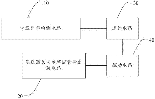
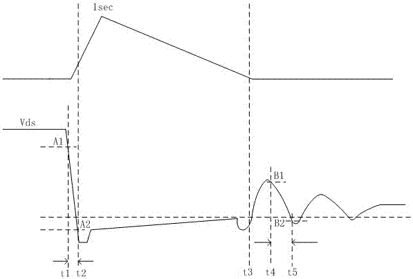
[0034] The present invention provides a control circuit of a synchronous rectifier tube. By setting a voltage slope detection circuit, the slope of the voltage change of the drain of the synchronous rectifier tube is detected, and it is accurately distinguished whether the change of the drain terminal voltage is caused by the shutdown of the main power tube of the primary side or It is caused by resonance after the synchronous rectifier is turned off, which prevents the synchronous rectifier from being turned on by mistake due to resonance.

[0035] In order to make the object, technical solution and effect of the present invention more clear and definite, the present invention will be further described in detail below with reference to the accompanying drawings and examples. It should be understood that the specific embodiments described here are only used to explain the present invention, not to limit the present invention.

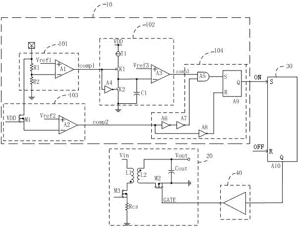
[0036] see figure 1 A synchronous rectifier con...


PUM


Abstract

The invention discloses a synchronized rectifier tube control circuit, comprising: a voltage slope detection circuit, a transformer and synchronized rectifier output stage circuit, a logic circuit and a driving circuit wherein the voltage slope detection circuit, the logic circuit, the driving circuit and the transformer and synchronized rectifier output stage circuit are connected in sequence. According to the invention, through the arrangement of the voltage slope detection circuit to detect the slope for the voltage variation of the synchronized rectifier tube's drain electrode, it is possible to accurately tell the cause of the voltage variation at the drain electrode by the closing of the main power tube at the primary side from the cause of the resonance oscillation by the closing of the synchronized rectifier tube so as to avoid the wrong start of the synchronized rectifier tube due to oscillation and to further realize the right start of the synchronized rectifier tube.

Description

technical field [0001] The invention relates to the field of power tube drive, in particular to a control circuit of a synchronous rectifier tube. Background technique [0002] Switching power supply technology has increasingly stringent requirements on efficiency. In order to improve the efficiency of switching circuits, synchronous rectification MOS tubes are often used to replace freewheeling diodes. [0003] However, in the case that the synchronous rectification MOS tube and the main switch signal of the primary side do not communicate, how to correctly turn on the synchronous rectification MOS tube becomes a key technology. [0004] Immediately after the main power tube of the primary side is turned off, the secondary side transformer starts freewheeling through the body diode of the synchronous rectifier. At the same time, the synchronous rectifier needs to be turned on quickly to reduce the freewheeling time of the body diode and improve efficiency. The existing syn...

Claims


Application Information

Patent Timeline
Patent Type & Authority Applications(China)
IPC IPC(8): H02M3/335H02M1/36
CPCH02M1/36H02M3/33592Y02B70/10
Inventor 宋利军白文利
Owner 无锡市稳先微电子有限公司
Why Eureka
Try Eureka