Emulsifying equipment for cosmetic production

A technology of emulsification equipment and cosmetics, applied in chemical instruments and methods, chemical/physical processes, mixers with rotating stirring devices, etc., can solve problems such as low shear rate, insufficient impact force of material flow, small operating area, etc. Achieve the effects of improving the quality of finished products, ensuring uniform mixing, and improving practicability

Inactive Publication Date: 2017-07-14
泉州惠安长圣生物科技有限公司
View PDF6 Cites 0 Cited by
  • Summary
  • Abstract
  • Description
  • Claims
  • Application Information

AI Technical Summary

Problems solved by technology

[0003] In order to facilitate the observation of the internal operation of the emulsification equipment, an observation mirror is usually installed on the pot cover of the emulsification equipment. During the stirring process of the rotor rotation, the material in the emulsification tank is easy to splash on the observation mirror, so that the staff cannot observe the operating conditions in the emulsification tank. Moreover, the existing emulsification machine has a single structure and can only be sheared by the rotation of the rotor. , resulting in insufficient impact force of material flow, low shear rate, small working area, and some large particles are deposited at the bottom, resulting in a dead angle of stirring, so that the material at the bottom cannot be sheared and mixed with other substances, so that it cannot play a good role. Emulsification operations affect the quality of cosmetic products and reduce the practicability of equipment

Method used


Image

  • Emulsifying equipment for cosmetic production
  • Emulsifying equipment for cosmetic production
  • Emulsifying equipment for cosmetic production

Examples


Embodiment Construction

[0030] The present invention is described in further detail now in conjunction with accompanying drawing. These drawings are all simplified schematic diagrams, which only illustrate the basic structure of the present invention in a schematic manner, so they only show the configurations related to the present invention.

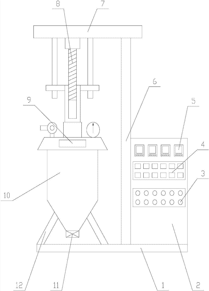
[0031] Such as Figure 1-Figure 6 As shown, an emulsification equipment for cosmetics production includes a base 1, a pillar 6, a control cabinet 2 and an emulsification mechanism, the pillar 6 is fixed above the base 1, and the control cabinet 2 is arranged on one side of the pillar 6 , the emulsification mechanism is arranged on the other side of the pillar 6, and the control cabinet 2 is provided with a number of indicator lights 3, a number of control buttons 4 and a number of detection instruments 5;

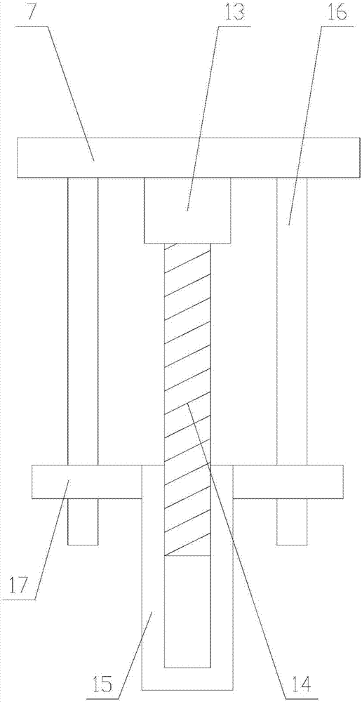
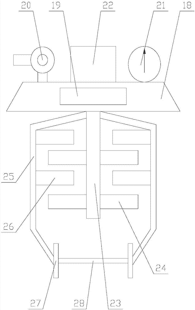
[0032] Described emulsifying mechanism comprises machine base 7, elevating mechanism 8, pot cover device 9, emulsifying cylinder 10 and several legs 12 su...


PUM


Abstract

The invention relates to emulsifying equipment for cosmetic production. The emulsifying equipment comprises an emulsifying mechanism and an emulsifying mechanism pot cover, wherein a pot cover device comprises two auxiliary emulsifying units; each auxiliary emulsifying unit comprises a side lever and a stirring unit; each stirring unit comprises a third drive motor, a first drive wheel, a lifting frame and a plurality of driving teeth; a cleaning mechanism is arranged in the pot cover and comprises a cleaning block and cleaning units arranged at two sides of the cleaning block; and each cleaning unit comprises a fourth drive motor, a second drive wheel, a fixed block, a fixed frame, a clamping plate and a connecting rod. According to the emulsifying equipment for cosmetic production, the cleaning block is driven to move on the surface of an observation mirror for cleaning through the cleaning units, so that a worker can conveniently observe the operating condition of cosmetic production of an emulsifying cylinder; not only that, a stirring plate moves up and down through the stirring units, and rising of raw materials at the bottom of the emulsifying cylinder is facilitated, so that a stirring dead corner is avoided in the emulsifying process, uniform mixing is ensured and the quality of a finished product in cosmetic production and the practicability of equipment are improved.

Description

technical field [0001] The invention relates to the field of cosmetic production equipment, in particular to an emulsification equipment for cosmetic production. Background technique [0002] Emulsification equipment is mainly a device developed for the incompatibility of water and oil phases in the production process of cosmetics companies. The rotor and stator of the homogenizing head rotate at a high speed of 2800 revolutions per minute to fully break and mix the materials evenly. So that the water phase and oil phase materials are blended together. The emulsification equipment shears, disperses, and impacts the materials through the high-speed rotation of the homogenizing head connected to the engine, so that the materials will become more delicate and promote the blending of oil and water. It is widely used in cosmetics, shower gels, sunscreens, etc. Lots of cream products. [0003] In order to facilitate the observation of the internal operation of the emulsification...

Claims


Application Information

Patent Timeline
IPC IPC(8): B01F7/16B01F3/08B01F13/06B01F15/00
CPCB01F23/43B01F27/192B01F27/806B01F33/70B01F35/12B01F35/20B01F35/413B01F35/45B01F35/43
Inventor 吴丽清
Owner 泉州惠安长圣生物科技有限公司
Why Eureka
Try Eureka