Automatic glue brushing device for brake pad manufacture

A brake pad and glue brushing technology, which is applied to the device and coating of the surface coating liquid, can solve the problems of difficult cleaning, low practicability, and easy contamination of workers' clothes or skin by the colloid

Inactive Publication Date: 2017-07-14
重庆云瑞智能自动化设备有限公司
View PDF7 Cites 35 Cited by
  • Summary
  • Abstract
  • Description
  • Claims
  • Application Information

AI Technical Summary

Problems solved by technology

[0005] In order to overcome the shortcomings of labor and material resources and low practicability, the colloid is easy to stain the clothes or skin of workers, and it is difficult to clean or cause damage to human skin, the technical problem to be solved by the present invention is to provide an automatic glue brushing with simple operation And automatic glue brushing device for brake pad production with high safety

Method used


Image

  • Automatic glue brushing device for brake pad manufacture
  • Automatic glue brushing device for brake pad manufacture
  • Automatic glue brushing device for brake pad manufacture

Examples


Embodiment 1

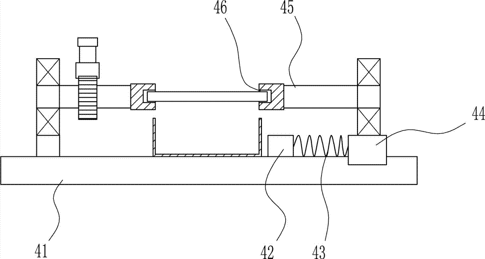
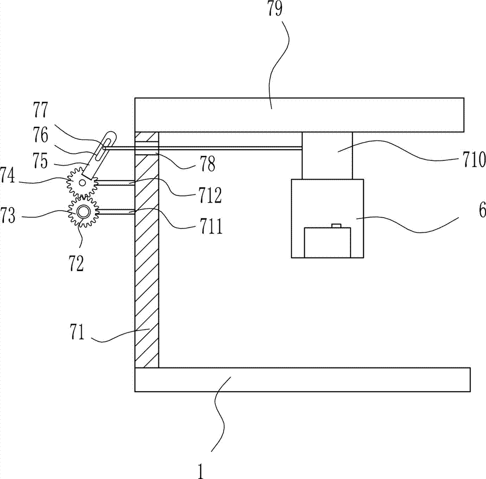
[0035] An automatic glue brushing device for brake pad production, such as Figure 1-7 As shown, it includes a bottom plate 1, an anti-glue frame 2, a rotating mechanism 3, a clamping mechanism 4, a lifting mechanism 5, a glue discharge mechanism 6, a front and rear moving mechanism 7, and a brush 8. The top surface of the bottom plate 1 is arranged sequentially from back to front. There are forward and backward moving mechanism 7, rotating mechanism 3 and clamping mechanism 4. Lifting mechanism 5 is arranged in front of the bottom of forward and backward moving mechanism 7. Glue discharging mechanism 6 is arranged on the right side and bottom of lifting mechanism 5. Brush is arranged at the bottom of glue discharging mechanism 6. 8. The glue discharging mechanism 6 is located directly above the clamping mechanism 4.

Embodiment 2

[0037] An automatic glue brushing device for brake pad production, such as Figure 1-7 As shown, it includes a bottom plate 1, an anti-glue frame 2, a rotating mechanism 3, a clamping mechanism 4, a lifting mechanism 5, a glue discharge mechanism 6, a front and rear moving mechanism 7, and a brush 8. The top surface of the bottom plate 1 is arranged sequentially from back to front. There are forward and backward moving mechanism 7, rotating mechanism 3 and clamping mechanism 4. Lifting mechanism 5 is arranged in front of the bottom of forward and backward moving mechanism 7. Glue discharging mechanism 6 is arranged on the right side and bottom of lifting mechanism 5. Brush is arranged at the bottom of glue discharging mechanism 6. 8. The glue discharging mechanism 6 is located directly above the clamping mechanism 4.

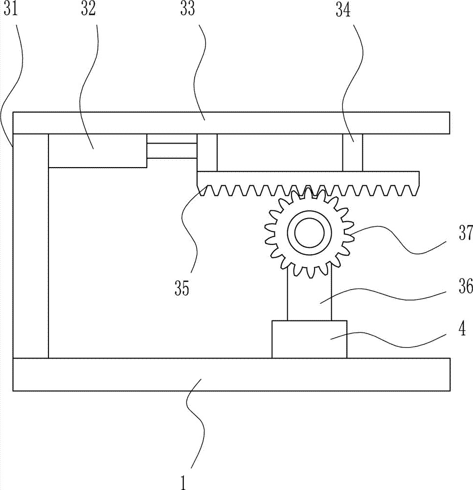
[0038] Turning mechanism 3 comprises pole 31, electric push rod 32, first slide rail 33, first slide block 34, first rack 35, first bearing seat 36, first gear ...

Embodiment 3

[0040] An automatic glue brushing device for brake pad production, such as Figure 1-7 As shown, it includes a bottom plate 1, an anti-glue frame 2, a rotating mechanism 3, a clamping mechanism 4, a lifting mechanism 5, a glue discharge mechanism 6, a front and rear moving mechanism 7, and a brush 8. The top surface of the bottom plate 1 is arranged sequentially from back to front. There are forward and backward moving mechanism 7, rotating mechanism 3 and clamping mechanism 4. Lifting mechanism 5 is arranged in front of the bottom of forward and backward moving mechanism 7. Glue discharging mechanism 6 is arranged on the right side and bottom of lifting mechanism 5. Brush is arranged at the bottom of glue discharging mechanism 6. 8. The glue discharging mechanism 6 is located directly above the clamping mechanism 4.

[0041] Turning mechanism 3 comprises pole 31, electric push rod 32, first slide rail 33, first slide block 34, first rack 35, first bearing seat 36, first gear ...


PUM


Abstract

The invention relates to a glue brushing device, in particular to an automatic glue brushing device for brake pad manufacture. The automatic glue brushing device for the brake pad manufacture carries out automatic glue brushing and is simple to operate and high in safety degree. The automatic glue brushing device for the brake pad manufacture comprises a bottom plate, a glue prevention frame, a rotating mechanism, a clamping mechanism, a lifting mechanism, a glue discharge mechanism and the like; a forward and backward movement mechanism, the rotating mechanism and the clamping mechanism are arranged on the top surface of the bottom plate from back to front sequentially; the lifting mechanism is arranged in front of the bottom of the forward and backward movement mechanism; the glue discharge mechanism is arranged on the right side and at the bottom of the lifting mechanism; and a hair brush is arranged at the bottom of the glue discharge mechanism. The effects of the automatic glue brushing and high safety are achieved, the rotating mechanism can rotate a brake pad so that the brake pad can be changed to the non-brushed surface to be coated with glue, and the position of the brake pad is fixed through the clamping mechanism.

Description

technical field [0001] The invention relates to a glue brushing device, in particular to an automatic glue brushing device for making brake pads. Background technique [0002] Brake pads are generally composed of steel plates, adhesive insulation layers and friction blocks. The steel plates must be painted to prevent rust. During the painting process, SMT-4 furnace temperature tracker is used to detect the temperature distribution during the painting process to ensure the quality. The heat insulation layer is composed of materials that do not conduct heat, and the purpose is heat insulation. The friction block is composed of friction material and adhesive, which is squeezed on the brake disc or brake drum to generate friction during braking, so as to achieve the purpose of vehicle deceleration and braking. Due to friction, the friction block will be gradually worn, generally speaking, the lower the cost of the brake pads, the faster the wear. [0003] During the production...

Claims


Application Information

Patent Timeline
Patent Type & Authority Applications(China)
IPC IPC(8): B05C1/02B05C11/10B05C13/02
CPCB05C1/025B05C11/1002B05C13/02
Inventor 不公告发明人
Owner 重庆云瑞智能自动化设备有限公司
Why Eureka
Try Eureka