
Device for preventing glaze slip from adhering to bottoms of ceramic tile blanks and control method of device

A glazing device and ceramic tile technology, which is applied in the direction of manufacturing tools, ceramic molding machines, etc., can solve the problems of glaze waste, low strength of floor tiles, and mismatching speed of conveying devices, etc., and achieve unique design effects

Pending Publication Date: 2017-07-14
JIANGXI HEMEI CERAMICS
View PDF9 Cites 14 Cited by
  • Summary
  • Abstract
  • Description
  • Claims
  • Application Information

AI Technical Summary

Problems solved by technology

However, due to the relatively low strength of the floor tiles and adobe, although the power of the first conveying device and the second conveying device are the same, it cannot guarantee that the running speed of the two conveying devices is consistent, and the speed of the two conveying devices does not match. When the first conveying device runs to the second conveying device, there will be small vibrations, resulting in dark cracks and even cracks in the bricks. Therefore, this device is more suitable for glazed wall tiles that have no elasticity after biscuit firing
Patent CN201510034943.0 discloses a glaze-saving device, which dents the conveyor belt and installs a glaze recovery device in the dent area, which can solve the problem of glaze waste on the conveyor belt
This device solves the problem of the synchronization of the belts at both ends of the concave area, but it is limited to the situation that the belts at both ends are under the same load, and the glaze slurry flows down and covers the surface of the bricks, which has a downward impact on the bricks, so the bricks pass through the depression. There are also vibrations in the area, which may still cause dark cracks in the bricks

Method used


Image

  • Device for preventing glaze slip from adhering to bottoms of ceramic tile blanks and control method of device
  • Device for preventing glaze slip from adhering to bottoms of ceramic tile blanks and control method of device

Examples


Embodiment Construction

[0048] The present invention will be further described below in conjunction with the accompanying drawings and specific embodiments.

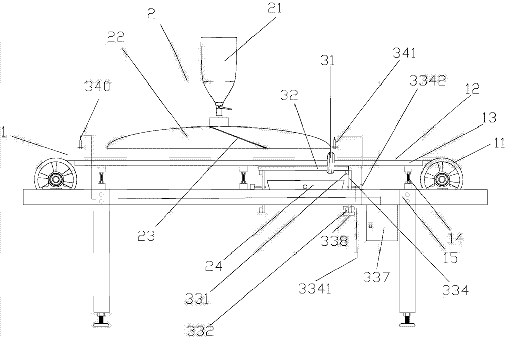
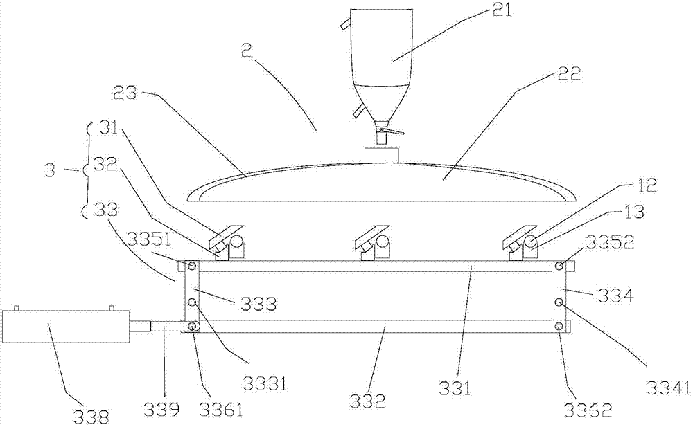
[0049] refer to figure 1 As shown, in order to achieve the above purpose, the device for preventing the glaze slurry from sticking to the bottom of the tile body according to the embodiment of the present invention adopts the following technical scheme: the device for preventing the glaze slurry from sticking to the bottom of the tile body includes a glaze line device 1, a glaze device 2 and a blocking A glaze device 3, the glaze line device 1 is located below the glaze device 2, and the glaze retaining device 3 is located below the glaze position of the glaze device 2;

[0050] The glaze line device 1 includes a pulley 11, a glaze line belt 12, a belt bracket 13, a support rod 14, and a glaze line bracket 15. The pulley 11 drives the glaze line belt 12 to run, and the glaze line belt 12 is embedded in In the belt bracket 13, the belt bracket ...


PUM


Abstract

The invention relates to the field of ceramic tile production and manufacturing in the ceramic industry, in particular to a device for preventing glaze slip from adhering to the bottoms of ceramic tile blanks and a control method of the device. The device comprises a glaze line unit, a glaze pouring unit and a glaze stop unit, wherein the glaze stop unit comprises glaze stop troughs, glaze baffle fixing rods and a transmission mechanism, the glaze stop troughs are connected with the transmission mechanism through the glaze baffle fixing rods, and the glaze stop troughs are obliquely arranged above glaze line belts. When the ceramic tile blanks on the glaze line belts leave the positions below the glaze pouring unit, the oblique glaze stop troughs move upwards and stop moving when the tops of the glaze stop troughs are located over the glaze line belts, at the moment, the glaze slip flowing down from a bell cover returns to a glaze receiving plate without flowing onto the glaze line belts, and therefore, the effect that the glaze slip is prevented from adhering to the bottoms of the ceramic tile blanks moving on the glaze line belts is guaranteed; and as the glaze material flowing down is not contaminated, the glaze material can be recycled, and waste and environment pollution are avoided.

Description

technical field [0001] The invention relates to the field of ceramic tile production and manufacturing in the ceramic industry, in particular to a device for preventing glaze slurry from sticking to the bottom of a tile body and a control method thereof. Background technique [0002] In the prior art, in the production process of ceramic tiles, glazing is one of the important technical links in the production process. At present, bell-jar glazing and linear glazing are widely used in the industry, that is, the glazing device is installed above the production glaze line, and the glazed line belt is used to transport the ceramic tile body through the lower part of the glazing device. Glaze covers the surface of the tile body. In order to ensure the stability of production, the glazer works continuously to flow down the glaze, while the tile body passes through the glazer intermittently, so when there is no brick passing through the glazer, the glaze flows from the glazer The...

Claims


Application Information

Patent Timeline
IPC IPC(8): B28B11/04
CPCB28B11/044
Inventor 李文军潘超宪邓江文杨庆霞罗荣飞
Owner JIANGXI HEMEI CERAMICS
Learn More