Two-way movement cam shaping mechanism

A technology of forming mechanism and cam, applied in the direction of packing/bundling items, packaging, wrapping items, etc., can solve the problems of unadjustable pressing force, too small or too large pressing force, etc., to avoid insufficient pressure and avoid wrinkling The effect of overloading the device

Pending Publication Date: 2017-07-14
上海江南制药机械有限公司
View PDF10 Cites 1 Cited by
  • Summary
  • Abstract
  • Description
  • Claims
  • Application Information

AI Technical Summary

Problems solved by technology

[0004] In order to solve the problem that the pressing force of the existing cam forming mechanism cannot be adjusted, the pressing force is too small or too large.

Method used


Image

  • Two-way movement cam shaping mechanism
  • Two-way movement cam shaping mechanism
  • Two-way movement cam shaping mechanism

Examples


Embodiment

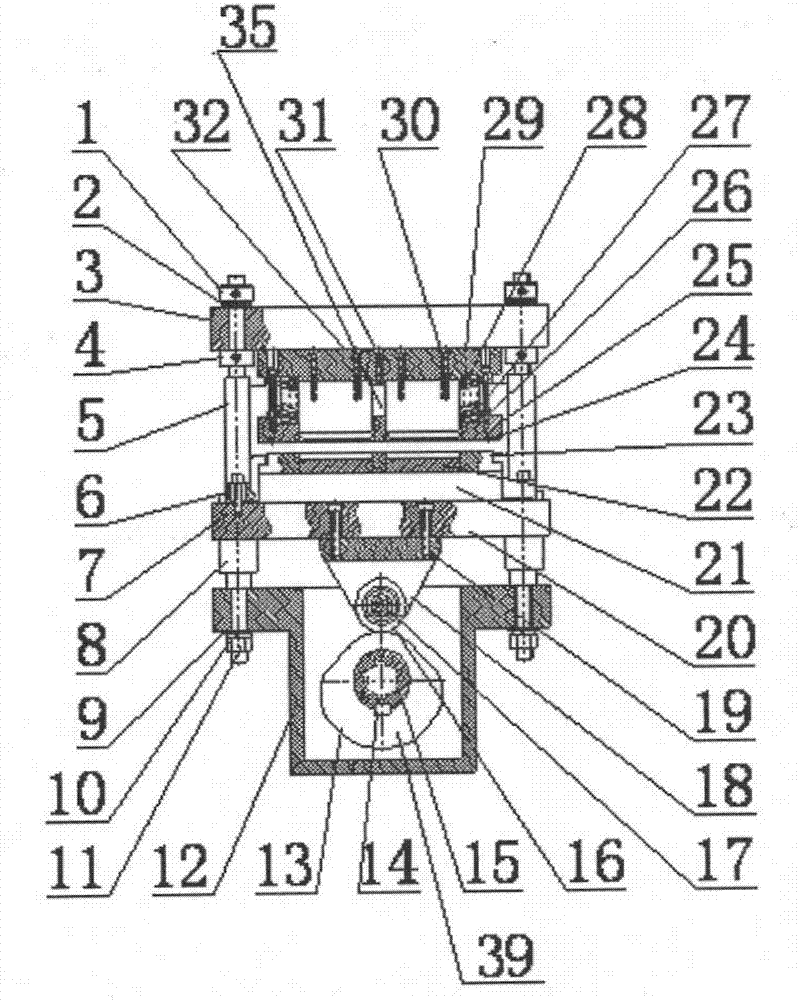
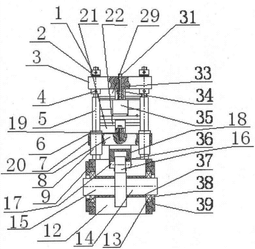
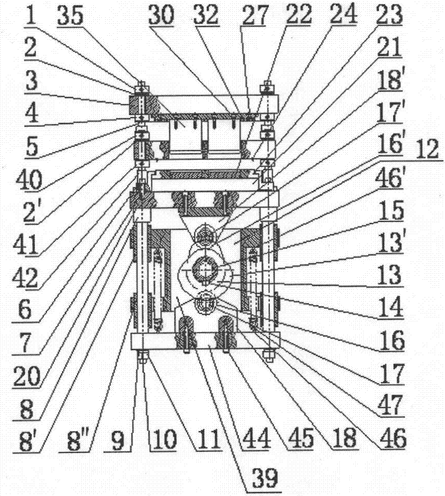
[0025] Such as image 3 , 4 As shown, it is a two-way action cam forming mechanism provided by the present invention. The first cam 13 and the two second cams 13' are installed on the cam spline sleeve 15 according to the relative positions in the figure, and additional cams are installed between adjacent cams. Cam spacer one 37, put cam spacer two 37' on the outer sides of the cams on both sides, separate cam one 13 and cam two 13, then press flat key 14 into the keyway of cam spline sleeve 15, cam The spline sleeve 15 is installed on the cam box 12 through the bearing 38 and the bearing cover 39; the first roller 16 and the second roller 16' are respectively installed on the roller seat through the first roller mandrel 17 and the second roller mandrel 17' One 18, Roller seat 2 18', Roller spacer 136 / Roller spacer 2 is installed between Roller 16 / Roller 2 16' and Roller seat 18 / Roller seat 2 18' 36'; adjust the position of the roller 2 16' to be tangent to the cam 13, insta...


PUM


Abstract

The invention discloses a two-way movement cam shaping mechanism. The two-way movement cam shaping mechanism comprises a cam case, a cam spline housing is arranged in the cam case, a punch assembly is arranged above the cam case and comprises a cover plate, and the cover plate is fixedly connected with the cam case through guide columns. A punch bottom plate is arranged below the cover plate, a duralumin punch and pressing plate dies are arranged below the punch bottom plate, the punch bottom plate is connected with a lower module through a punch locating plate, lower duralumin dies are arranged outside the lower module, the lower duralumin dies are fixedly connected with a guide plate through a lower duralumin die pressing plate, a first roller base is arranged below the guide plate, and a first roller is arranged on the first roller base. The two-way movement cam shaping mechanism is characterized in that another punch assembly is arranged below the cam case and comprises a bottom plate, a second roller base is arranged on the bottom plate, and a second roller is arranged on the second roller base; the second roller is tangent to a first cam; the first roller is tangent to a second cam. The two-way movement cam shaping mechanism can realize compacting and shaping of packing materials when a bubble cap machine runs, compaction force can be freely adjusted, and insufficient pressure or excessive pressure is avoided.

Description

technical field [0001] The invention relates to a bidirectionally acting cam forming mechanism, in particular to a mechanism for automatically compressing packaging materials and forming automatically by a bidirectional cam mechanism. Background technique [0002] Existing cam forming mechanism such as figure 1 , 2 Shown, it comprises cam box 12, is provided with cam spline sleeve 15 in cam box 12, and cam spline sleeve 15 is connected with cam 13 by flat key 14; Guide column 5 is fixed on the cover plate 3 on the cam box 12, cover plate 3 is connected punch base plate buckle 34 by screw 5 31, and punch base plate buckle 34 is embedded with nut 5 33; There is a hard aluminum punch 35, the top of the guide post 5 and the cover plate 3 are fixed by the nuts 1 and 2 4 on the upper and lower sides of the cover plate 3, and a disc spring 2 is installed between the nut 1 and the cover plate 3, The bottom end of guide post 5 is fixed by flat pad 9, spring washer 10, guide post l...

Claims


Application Information

Patent Timeline
Patent Type & Authority Applications(China)
IPC IPC(8): B65B11/50
CPCB65B11/50
Inventor 杨坚林昌平季海艇胡传庆何勇李华光方小钢
Owner 上海江南制药机械有限公司
Why Eureka
Try Eureka