Eureka AIR delivers breakthrough ideas for toughest innovation challenges, trusted by R&D personnel around the world.

Rail type mobile cantilever crane

A cantilever crane and track-type technology, which is applied to cranes and other directions, can solve the problems of low work efficiency, large number of construction personnel, and strong labor force, etc., and achieve the effects of small space occupation, good stability and practical functions

Inactive Publication Date: 2017-07-14
HEFEI KIWI HEAVY MACHINERY CO LTD
View PDF6 Cites 2 Cited by
  • Summary
  • Abstract
  • Description
  • Claims
  • Application Information

AI Technical Summary

Problems solved by technology

[0004] In the process of blast furnace construction, the carbon bricks and ceramic cup combined bricks used in the furnace bottom masonry are relatively large in size and weight, and the weight of a single brick can reach hundreds or even thousands of kilograms. The method of reversing the chain not only requires a large number of construction personnel, but also requires strong labor and low work efficiency, and it cannot be placed in place at one time. The construction is very difficult. The existing cantilever cranes have relatively low functions and are not convenient to use. Moreover, for some heavier loads, the support column will tilt, and the hoist mechanism can only move left and right in a single way, with a single function

Method used


Image

  • Rail type mobile cantilever crane
  • Rail type mobile cantilever crane

Examples


Embodiment Construction

[0020] In order to make the technical means, creative features, goals and effects achieved by the present invention easy to understand, the present invention will be further described below in conjunction with specific embodiments.

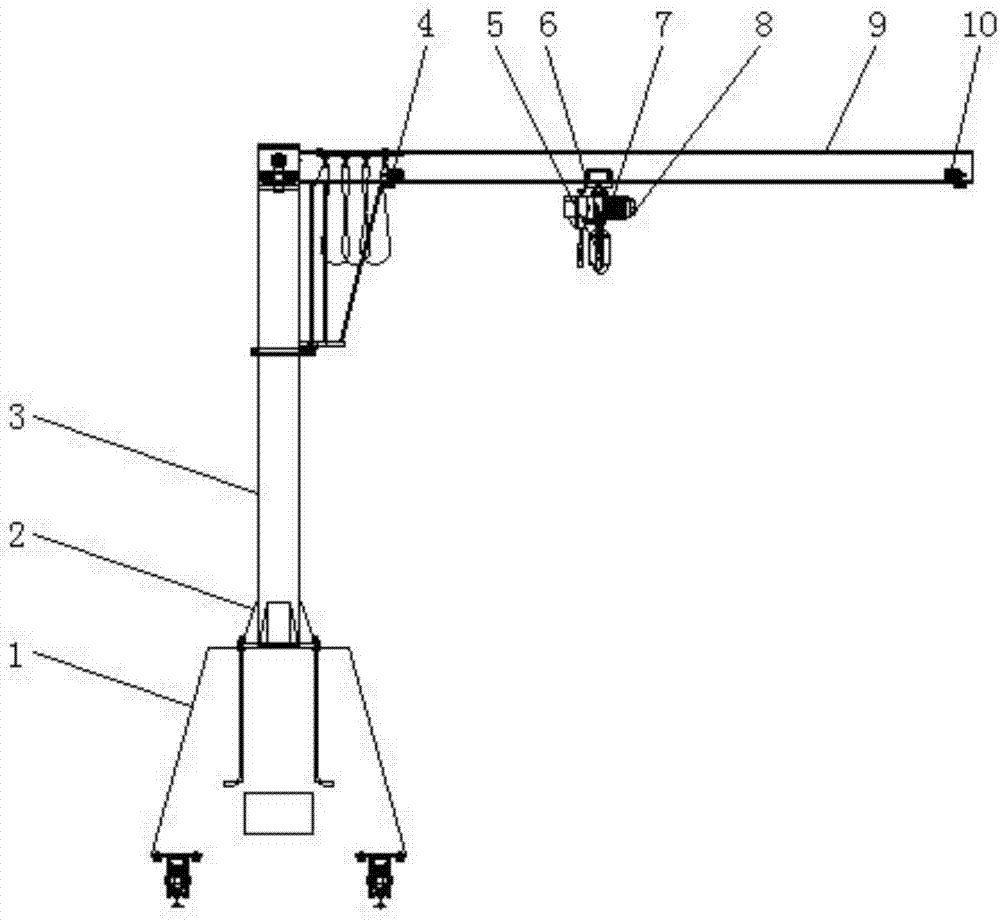
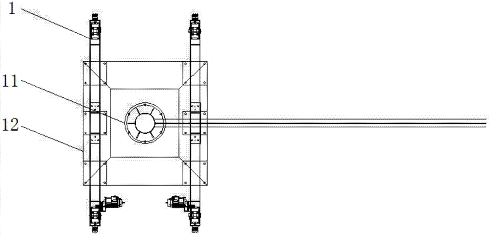
[0021] like Figure 1-2 As shown, the track-type mobile cantilever crane includes a base 1, the top of the base 1 is fixedly connected with a support frame 3, and the top end of the support frame 3 is fixedly connected with a rotating shaft seat 12, and the middle position of the rotating shaft seat 12 is There is a rotating shaft 11, one end of the rotating shaft 11 is clamped with a cantilever 9, the bottom end of one side of the cantilever 9 is clamped with a gourd mechanism 7, and the top end of the gourd mechanism 7 is sleeved with a moving block 6, so One end of the gourd mechanism 7 is clamped with a driving mechanism 8 , and the bottom end of the gourd mechanism 7 is sleeved with a hook 5 , and the connection between the support frame 3 an...


PUM

PropertyMeasurementUnit
Rotation angleaaaaaaaaaa

Abstract

The invention discloses a rail type mobile cantilever crane. The rail type mobile cantilever crane comprises a base; the top of the base is fixedly connected with a support frame; the top end of the support frame is fixedly connected with a rotating shaft base; a rotating shaft is arranged in the middle position of the rotating shaft base; one end of the rotating shaft is connected with a cantilever in a clamping manner; the bottom end of one side of the cantilever is connected with a hoist mechanism in a clamping manner; a mobile block sleeves the top end of the hoist mechanism; one end of the hoist mechanism is clamped with a driving mechanism; a lifting hook sleeves the bottom end of the hoist mechanism; and the joint of the support frame and the base is fixedly connected with triangular fixed frames through bolts. The rail type mobile cantilever crane is less in occupied space; one set of end beams at the bottom is capable of driving the cantilever crane to longitudinally move; the cantilever can rotate by 360 degrees; the hoist mechanism on the cantilever realizes transverse movement and up-down movement of a load to achieve the load carrying purpose; a base counterweight is formed by casting concrete to achieve high self-weight and low cost; and when the load is lifted, the cantilever crane cannot topple, the stabilizing effect is good, and the function is practical.

Description

[0001] 【Technical field】 [0002] The invention relates to a mobile cantilever crane, in particular to a rail-type mobile cantilever crane. [0003] 【Background technique】 [0004] In the process of blast furnace construction, the carbon bricks and ceramic cup combined bricks used in the furnace bottom masonry are relatively large in size and weight, and the weight of a single brick can reach hundreds or even thousands of kilograms. The method of reversing the chain not only requires a large number of construction personnel, but also requires strong labor and low work efficiency, and it cannot be placed in place at one time. The construction is very difficult. The existing cantilever cranes have relatively low functions and are not convenient to use. Moreover, for some heavier loads, the support column will be tilted, and the hoist mechanism can only move left and right in a single way, and has a single function. [0005] 【Content of invention】 [0006] The main purpose of th...

Claims


Application Information

Patent Timeline
IPC IPC(8): B66C23/36B66C23/88B66C23/62
CPCB66C23/36B66C23/62B66C23/88
Inventor 黄浩龚子运王金龙
Owner HEFEI KIWI HEAVY MACHINERY CO LTD
Why Eureka
Eureka Blog
Learn More