
O-shaped steel bar connecting structure

A technology for connecting structures and steel bars, applied in the direction of structural elements, building components, building structures, etc., can solve the problems of missing key structures, heavy workload, and lagging control structures, and simplify the connection of steel bars and component joints. , The effect of reducing the project cost and reducing the use of materials

Inactive Publication Date: 2017-07-14
ANHUI TRANSPORTATION HLDG GRP CO LTD
View PDF6 Cites 9 Cited by
  • Summary
  • Abstract
  • Description
  • Claims
  • Application Information

AI Technical Summary

Problems solved by technology

After years of exploration, although this technology has been greatly developed and the demonstration effect is good, there are still many shortcomings: such as insufficient large-scale construction, absence of key structures, lagging control structure and lack of theoretical breakthroughs
[0003] The wet joint reinforcement connection between precast concrete components has always been a difficult problem in domestic design and construction: when the steel bars are lapped and welded according to the specifications, the wet joints are too wide and the workload is too large. If other connection methods are used, the connection The effect cannot be guaranteed

Method used


Image

  • O-shaped steel bar connecting structure
  • O-shaped steel bar connecting structure
  • O-shaped steel bar connecting structure

Examples


Embodiment 1

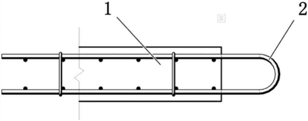
[0022] Such as figure 2 , Prefabricated concrete component 1, 24cm thick, with U-shaped steel bar 2 at the end, the connection of U-shaped steel bar 2 is welded, and the wet joint width of the connection is 50cm, the workload is too large, and the construction efficiency is low.

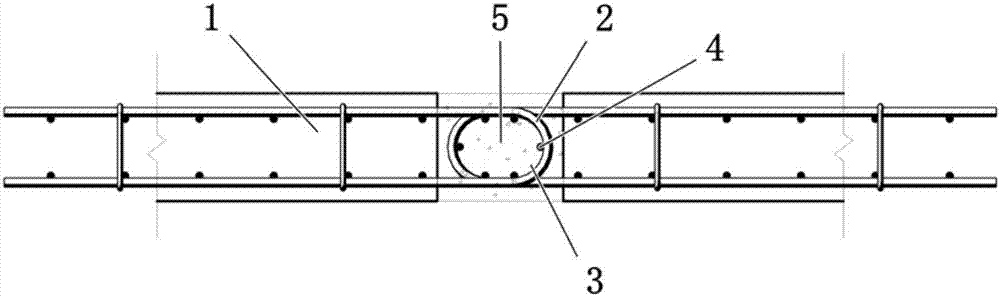
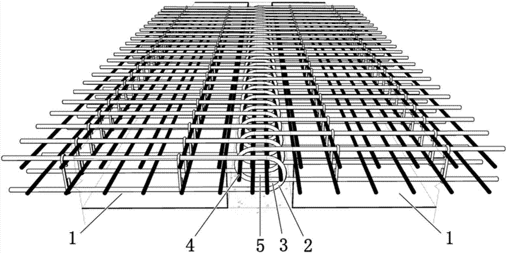
[0023] Such as figure 1 , image 3 Two rows of U-shaped steel bars 2 arranged on different prefabricated concrete components 1 are overlapped and intersected to form an O-shaped steel bar structure 3. The support pad steel bar 4 is arranged in the O-shaped steel bar structure 3, and the anchor is formed by pouring pressure-bearing concrete 5 The two rows of opposite U-shaped steel bars 2 are not welded, and they are intersected with each other, with a distance of 7.5 cm. The supporting steel bars 4 are arranged in the O-shaped steel bar structure 3 and bound to it, and the O-shaped steel bar structure 3 is connected in series. One piece, forming a net-shaped force-bearing surface, the diameter of ...

Embodiment 2

[0026] This embodiment is basically the same as Embodiment 1. The distance between the supporting steel bars used is 40 mm, and the diameter is 12 mm. They are arranged symmetrically on the O-shaped steel bars. The distance between the U-shaped steel bars is 75 mm. The axial center of the bearing concrete The standard value of compressive strength is 35Mpa.

Embodiment 3

[0028] This embodiment is basically the same as Embodiment 1. The distance between the supporting steel bars used is 150 mm, and the diameter is 25 mm. They are arranged symmetrically on the O-shaped steel bars. The distance between the U-shaped steel bars is 100 mm. The standard value of compressive strength is 40Mpa.


PUM


Abstract

The invention relates to an O-shaped steel bar connecting structure. The O-shaped steel bar connecting structure comprises two rows of U-shaped steel bars arranged on different concrete components. The two rows of the U-shaped steel bars are oppositely overlapped and crossed to form the O-shaped steel bar structure which is internally provided with a plurality of supporting cushion steel bars and forms anchorage-type connecting through pressure-bearing concrete pouring. According to the O-shaped steel bar connecting structure, a traditional mode and a force-transferring mechanism of steel bar connecting are changed, the width of a wet joint formed by connecting is greatly reduced to be less than half of the width of a non-welding wet joint of a traditional steel bar, steel bar connecting and component jointing are simplified, material using is reduced, engineering cost is reduced, the workload is greatly reduced, construction site quick connecting of factory precast concrete components is achieved, and development of a bridge girder industrial construction technology is promoted.

Description

technical field [0001] The invention belongs to the technical field of civil engineering, and in particular relates to an O-shaped steel bar connection structure. Background technique [0002] At present, adopting a structural point of view and an industrialized model to implement the construction of less soil, no soil, high efficiency, and low-cost projects at the level of scale and serialization is becoming the development direction of my country's green road construction. Among them, the complete set of technology for small and medium-sized structures is a key part of the implementation of green road construction and road industrialization. After years of exploration, although this technology has been greatly developed and the demonstration effect is good, there are still many shortcomings: such as insufficient large-scale construction, absence of key structures, lagging control structures, and lack of theoretical breakthroughs. [0003] The wet joint reinforcement conne...

Claims


Application Information

Patent Timeline
Patent Type & Authority Applications(China)
IPC IPC(8): E04B1/41E04C5/16
CPCE04B1/41E04B2001/4192E04C5/162
Inventor 胡可杨晓光陈发根王凯王胜斌梅应华吴平平梁长海吴志刚唐国喜窦巍魏民夏伟石雪飞阮欣刘志权
Owner ANHUI TRANSPORTATION HLDG GRP CO LTD
Learn More