Displacement Control Unit

A technology of control unit and control cylinder, which is applied in the direction of engine components, functional valve types, transportation and packaging, etc., can solve the problems of low control force energy level, large volume, unsafe, etc., and achieve the effect of easy operation

Active Publication Date: 2019-04-23
DANFOSS POWER SOLUTIONS GMBH & CO
View PDF9 Cites 0 Cited by
  • Summary
  • Abstract
  • Description
  • Claims
  • Application Information

AI Technical Summary

Problems solved by technology

However, this alternative reduces the level of energy used to generate control forces
Therefore, such explosion-proof design solutions usually have the following disadvantages: the limited energy is usually not enough to provide a high enough force for reliable, high-quality control / movement of the hydraulic unit
Therefore, the prior art solutions described above have the disadvantage of being relatively bulky and / or not intrinsically safe

Method used


Image

  • Displacement Control Unit
  • Displacement Control Unit
  • Displacement Control Unit

Examples


Embodiment Construction

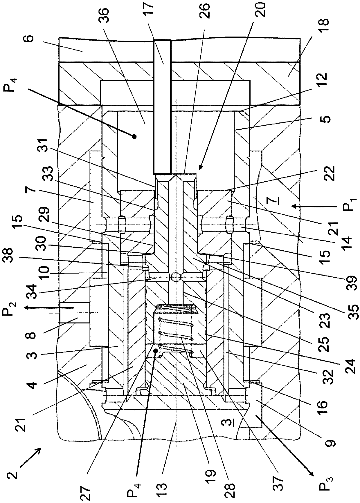
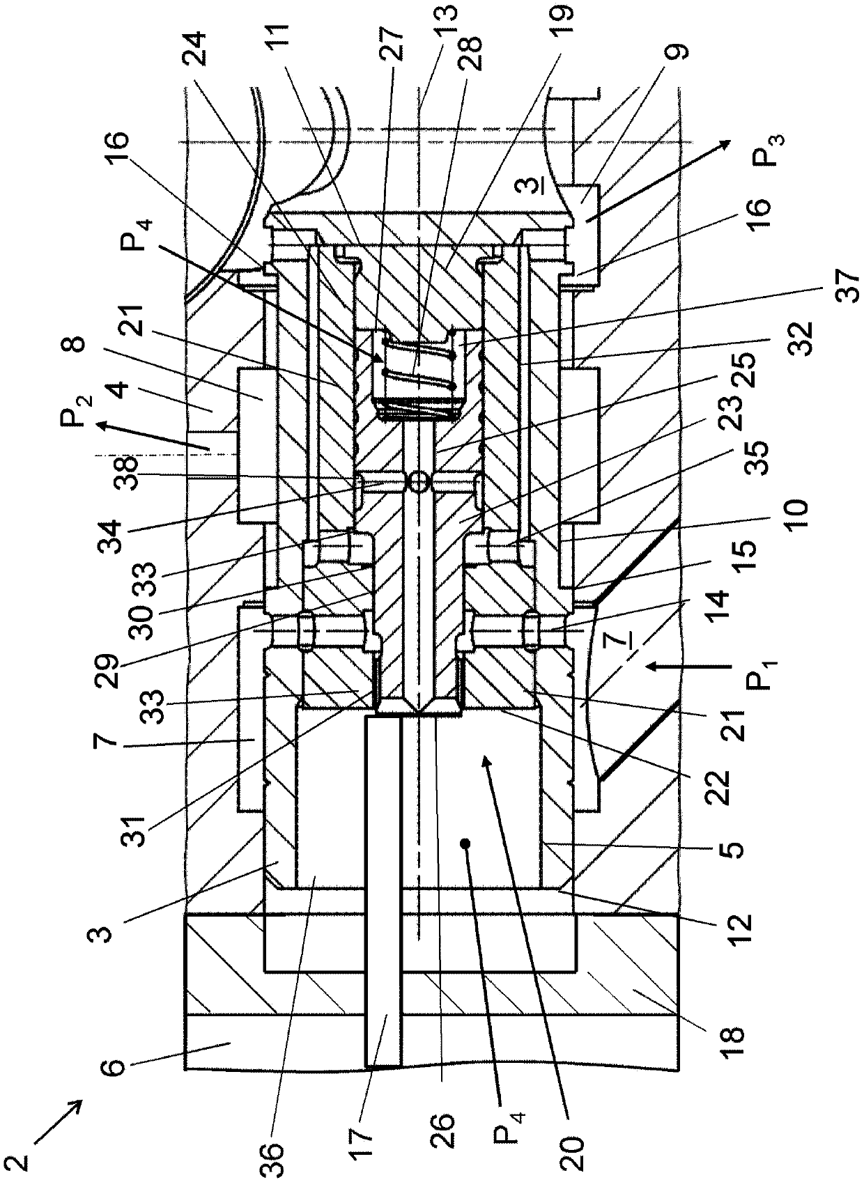
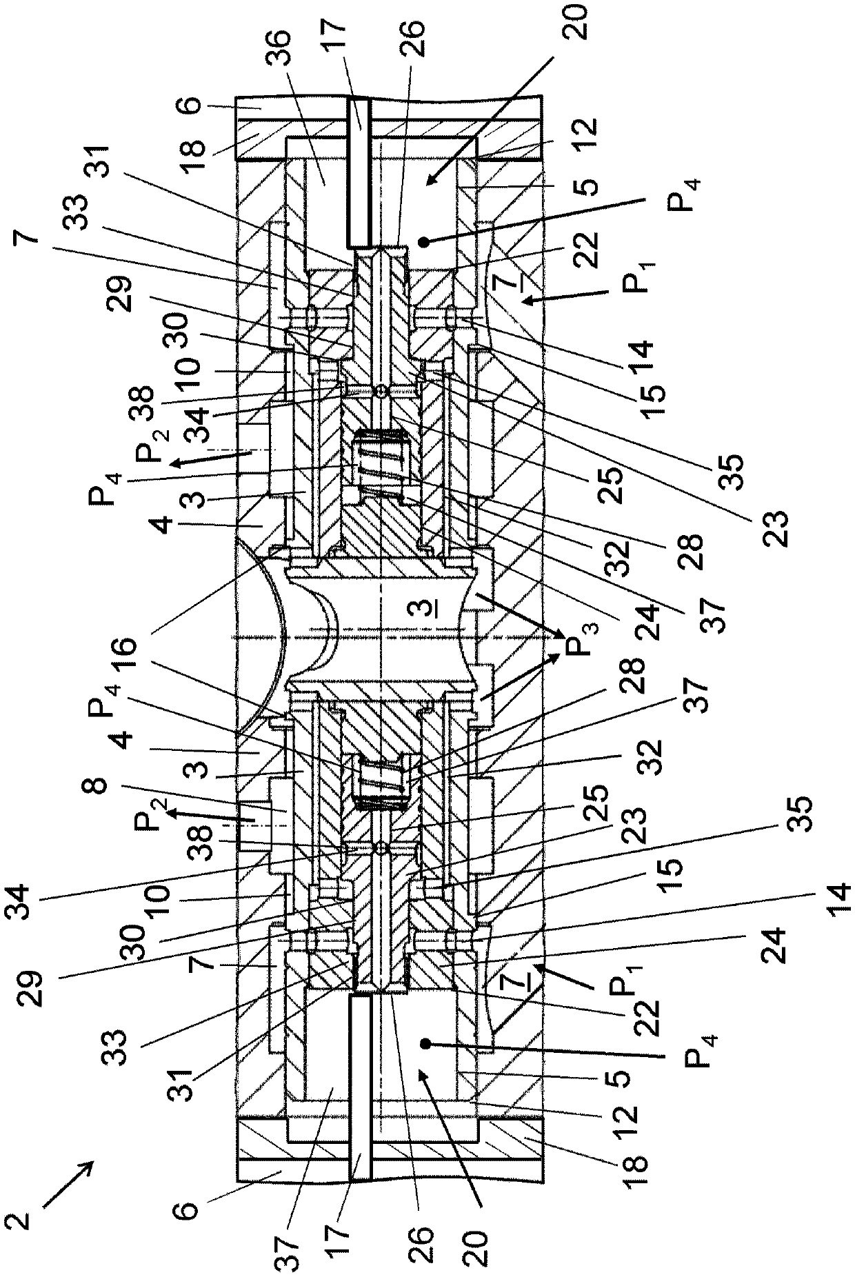
[0022] figure 1 A partial cross section of an embodiment of the control unit 2 according to the invention is shown. Shown is the right side of the substantially symmetrical control unit 2, where the control unit 2 includes a common control cylinder 4, and a movable and substantially symmetrical control piston 3 is provided in the cylinder 4, such as image 3 Shown. Figure 1-3 The control piston 3 exemplarily shown in is used for displacement control of a hydraulic unit (for example, a hydraulic pump or a motor with a reversible hydraulic fluid flow).

[0023] in figure 1 The right side of the control unit 2 shown in, shows the right half of the control piston 3 slidably guided inside the control cylinder 4. The intrinsically safe actuator 6 acts only and indirectly on the control piston 3 via the plunger 17. The displacement of the control piston 3 connects / disconnects some pipes for hydraulic fluid to adjust the displacement of the hydraulic unit. These connections are opened...


PUM


Abstract

A control unit (2) of a hydraulic unit comprising a control piston (3) slidably arranged in a control cylinder (4) for servo pressure at a first outlet (8) of the control unit (2) (P 2 ) to provide hydraulic fluid suitable for the displacement of the hydraulic unit. Servo pressure (P 2 ) is proportional to the sum of the internal force of the hydraulic unit and the operating force acting on the control unit (2). The hydraulic fluid provided at the outlet (8) is at the inlet (7) of the control unit (2) at the filling pressure (P 1 ) is supplied by the filling pressure supply. The control piston (3) has a blind hole (5) in the direction of the longitudinal axis (13) of the control unit (2), a pressure relief valve (20) is arranged in the blind hole (5) and serves as a pilot control unit, the pilot control unit has The double-sided pressure relief piston (23) is arranged in the blind hole (5) and is slidable relative to the control piston (3) by the actuator (6), so that the displacement of the pressure relief piston (23) is carried out by the actuator (6). , the reduced filling pressure as the hydraulic set pressure (P 4 ) acts on the intermediate front surface (26) and distal front surface (27) of the pressure relief piston (23) and on the front surface (12) of the control piston (3). The control piston (3) can pass through the set pressure (P 4 ) generated by the sum of the pressure and the force of the actuator (6) moves within the control cylinder (4).

Description

Technical field [0001] The present invention relates to a control unit including a control piston slidably arranged in a control cylinder to be able to guide hydraulic fluid to a servo unit of a controlled displacement hydraulic unit under servo pressure. The servo pressure provided at the first outlet of the control unit is proportional to the sum of the internal force on the control unit and the operating force acting on the control unit. Therefore, the hydraulic fluid guided to the outlet is provided by the filling pressure supply device supplied to the inlet of the control unit. Background technique [0002] Such control units are known for example from DE 102008050835A1 and DE 10127907A1. [0003] Hydraulic units and their components (for example, static pressure pumps, static pressure motors, static pressure valves, or power cylinders) are usually operated in explosive atmospheres or areas with explosion risks. Therefore, the hydraulic unit and its components must be design...

Claims


Application Information

Patent Timeline
Patent Type & Authority Patents(China)
IPC IPC(8): F15B13/044
CPCF15B13/044F15B13/0442Y10T137/86694F16K17/04F16K11/0716F15B15/1447F15B15/202
Inventor 托马斯·莱因哈特
Owner DANFOSS POWER SOLUTIONS GMBH & CO
Why Eureka
Try Eureka