Liquid nitrogen injection device for continuous high-speed wind tunnel cooling system

A high-speed wind tunnel, liquid nitrogen technology, applied in measuring devices, instruments, aerodynamic tests, etc., can solve problems such as overpressure and easy freezing of metal materials, and achieve good matching, rapid atomization and uniform spraying, design reasonable effect

Active Publication Date: 2017-07-14
NORTHWESTERN POLYTECHNICAL UNIV
View PDF3 Cites 9 Cited by
  • Summary
  • Abstract
  • Description
  • Claims
  • Application Information

AI Technical Summary

Problems solved by technology

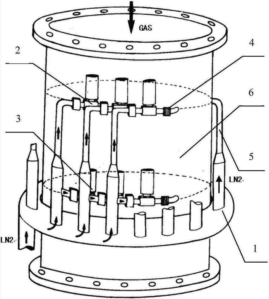
[0005]Aiming at the physical characteristics of liquid nitrogen, such as ultra-low temperature, fast evaporation, and large expansion coefficient, in order to solve the problem that the metal material of the wind tunnel body is easy to freeze and crack when liquid nitrogen is injected. In order to solve technical problems such as high pressure and other technical problems, a safe and efficient liquid nitrogen injection technology is established for the cooling system. According to the structural characteristics and operation mode of the continuous high-speed wind tunnel, this invention proposes a set of liquid nitrogen injection for the continuous high-speed wind tunnel cooling system. injection device

Method used


Image

  • Liquid nitrogen injection device for continuous high-speed wind tunnel cooling system
  • Liquid nitrogen injection device for continuous high-speed wind tunnel cooling system
  • Liquid nitrogen injection device for continuous high-speed wind tunnel cooling system

Examples


Embodiment Construction

[0031] Embodiments of the present invention are described in detail below, examples of which are shown in the drawings, wherein the same or similar reference numerals designate the same or similar elements or elements having the same or similar functions throughout. The embodiments described below by referring to the figures are exemplary and are intended to explain the present invention and should not be construed as limiting the present invention.

[0032]In describing the present invention, it should be understood that the terms "center", "longitudinal", "transverse", "length", "width", "thickness", "upper", "lower", "front", " Orientation indicated by rear, left, right, vertical, horizontal, top, bottom, inside, outside, clockwise, counterclockwise, etc. The positional relationship is based on the orientation or positional relationship shown in the drawings, which is only for the convenience of describing the present invention and simplifying the description, rather than i...


PUM


Abstract

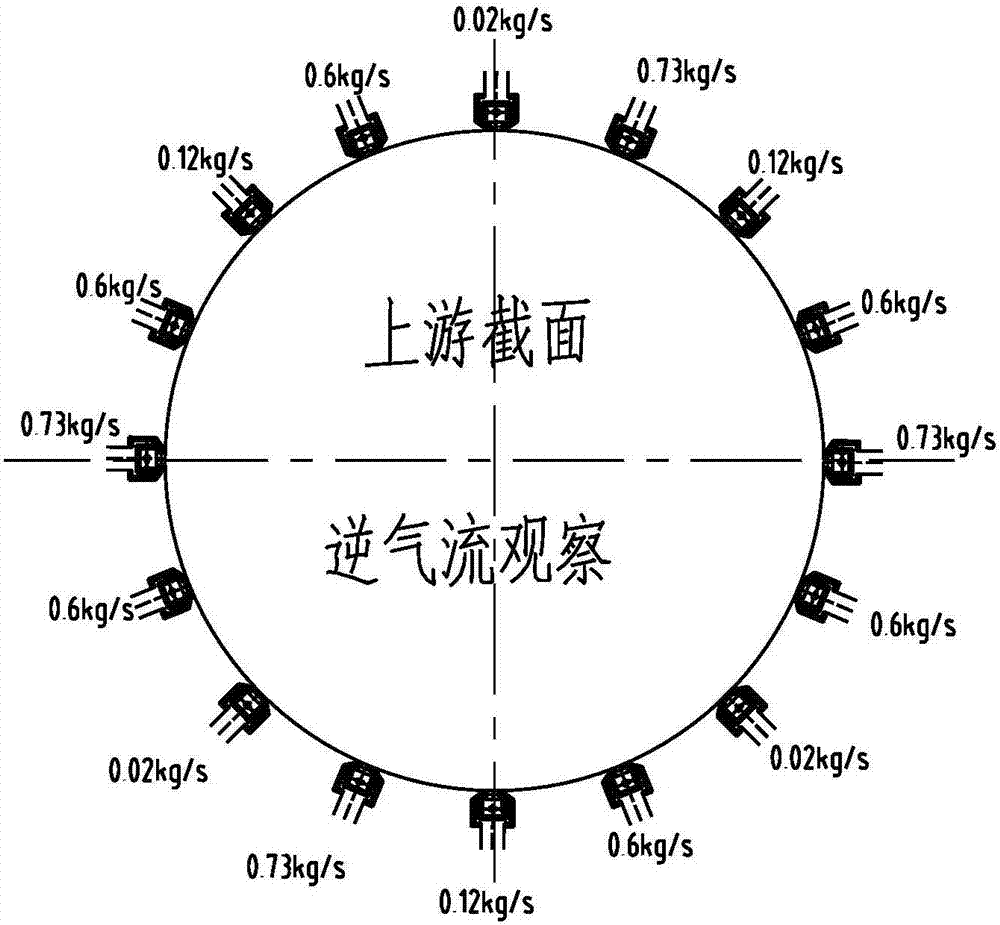
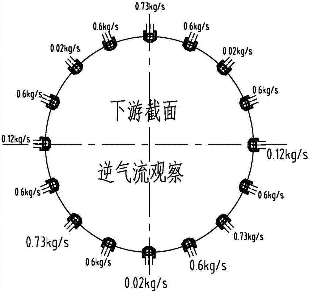
The invention proposes a liquid nitrogen injection device for a continuous high-speed wind tunnel cooling system, and the device comprises a liquid collection ring, an upstream liquid nitrogen nozzle block, and a downstream liquid nitrogen nozzle block. The liquid nitrogen injection device is installed in a liquid nitrogen injection experiment segment. The liquid collection ring is an annular low-temperature-resistant stainless steel pipe, and the internal diameter of the liquid collection ring is the same as the external diameter of an experimental wind tunnel at an installation position. The liquid collection ring is installed at the experimental wind tunnel in an annular manner, and is used for receiving the low-temperature liquid nitrogen from a main pipe and conveying the liquid nitrogen to the liquid nitrogen nozzle blocks. The upstream and downstream liquid nitrogen nozzle blocks are distributed along the air flow axis of the wind tunnel in a parallel manner. The distance between the upstream liquid nitrogen nozzle block and the upstream end face of the experimental segment is 0.61d, and the distance between the downstream liquid nitrogen nozzle block and the upstream end face of the experimental segment is 1.72d, wherein d is the internal diameter of the upstream end face of the experimental segment. The matching of the device with the whole cooling system of the wind tunnel is good. The technical scheme of the invention provides support for the building of the first Chinese continuous high-speed wind tunnel cooling system.

Description

technical field [0001] The invention relates to the design field of cryogenic liquid injection technology for closed containers, in particular to a liquid nitrogen injection device for a continuous high-speed wind tunnel cooling system. Background technique [0002] The Reynolds number is an important similar parameter for wind tunnel experiments to simulate the actual flight capabilities of aircraft. The difference between the experimental Reynolds number and the flight Reynolds number will lead to significant differences between the aerodynamic characteristics of the boundary layer transition, separation position, shock wave position, and strength obtained in the experiment and the actual flight state. As a result, the engineering application value of the experimental data is greatly reduced. In some cases it may not even work. Theoretically speaking, in order to make the wind tunnel experiment fully simulate the real flight state, the Reynolds number of the wind tunnel e...

Claims


Application Information

Patent Timeline
Patent Type & Authority Applications(China)
IPC IPC(8): G01M9/04
CPCG01M9/04
Inventor 李峰高超郗忠祥盛强郝东东李征
Owner NORTHWESTERN POLYTECHNICAL UNIV
Why Eureka
Try Eureka