Wireless charging magnetic coupling structure applied to multiple loads and circuit thereof

A technology of wireless charging and magnetic coupling, applied in circuits, circuit devices, transformer/inductor cores, etc., can solve the problems of insufficient capacity, large winding loss, low coupling coefficient, etc., achieve high power transmission efficiency, and relatively simple structure , the effect of high coupling coefficient

Inactive Publication Date: 2017-07-14
FUZHOU UNIV
View PDF19 Cites 9 Cited by
  • Summary
  • Abstract
  • Description
  • Claims
  • Application Information

AI Technical Summary

Problems solved by technology

[0013] A typical example is the patent "Wireless Power Transmission in Vehicles" (application number: 201480027153.3) of the American Wireless Power Company (WiTricity); The cost is high. For the receiving coil 2, although the winding turn length is reduced and the ring winding for receiving the magnetic field in the z-axis direction is added, if you want to reduce the receiving winding turn length in the x and y-axis directions, you must reduce the maximum length of the guiding core. The peripheral cross-sectional area will lead to excessive reluctance, and the ability to converge the magnetic field transmitted in the x and y directions is obviously insufficient, and the coupling coefficient in the x and y directions is not high. This is a pair of contradictions

Method used


Image

  • Wireless charging magnetic coupling structure applied to multiple loads and circuit thereof
  • Wireless charging magnetic coupling structure applied to multiple loads and circuit thereof
  • Wireless charging magnetic coupling structure applied to multiple loads and circuit thereof

Examples


Embodiment Construction

[0056] The present invention will be further described below in conjunction with the accompanying drawings and embodiments.

[0057] This embodiment provides a magnetic coupling coil for wireless charging, which is characterized in that it includes a transmitting coil and several receiving coils coupled with the transmitting coil, and the receiving coils are rectangular quadrature coils or double-king structure quadrature coils;

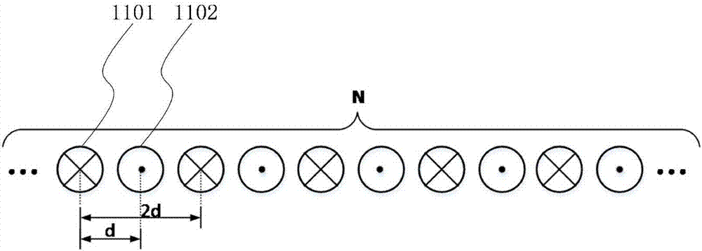
[0058] In this embodiment, the transmitting coil is a current return type planar rectangular coil, which is composed of several parallel wire segments (or wire groups), and the current directions of any adjacent wire segments (or wire groups) are opposite. The current direction is the same; Figure 1A Shown is a schematic diagram of the current flow of the transmitting coil, 1101 indicates that the current in the conductor flows in vertically on the paper, and 1102 indicates that the current in the conductor flows out vertically on the paper, so that ...


PUM


Abstract

The invention relates to a wireless charging magnetic coupling structure applied to multiple loads. The wireless charging magnetic coupling structure comprises a transmitting coil and a plurality of receiving coils, wherein the receiving coils are quadrature coils shaped like a Chinese character 'tian' and quadrature coils shaped like dual Chinese character 'wang'; the transmitting coil is formed by a plurality of lead groups which are parallel to each other; current directions in any adjacent lead groups are opposite; the quadrature coils shaped like a Chinese character 'tian' consist of a first magnetic core and a second magnetic core which are perpendicular to each other; third magnetic cores vertical to the first magnetic core and the second magnetic core are arranged at the ends of the first magnetic core and the second magnetic core respectively; first windings, second windings and third windings are arranged on the outer sides of the first magnetic core, the second magnetic core and four third magnetic cores respectively; the quadrature coils shaped like dual Chinese character 'wang' are subjected to secondary extension at the ends of the first magnetic core and the second magnetic core which are perpendicular to each other. The invention also relates to a circuit. The wireless charging magnetic coupling structure is capable of effectively and evenly receiving the energy of a magnetic field by the receiving coils in the range of the transmitting coil and has higher coupling coefficient and higher electric energy transmission efficiency.

Description

technical field [0001] The invention relates to a wireless charging magnetic coupling structure and circuit for multiple loads. Background technique [0002] Wireless power transmission technology has the characteristics of convenience, no mechanical loss, and no electric sparks. It has good application prospects in various special environments such as the interior of the human body, mines, high-voltage environments, underwater, and electric vehicles. It has been recognized by the academic community in recent years. and widespread attention from the business community. [0003] At present, the magnetic coupling structure of the wireless power transmission technology mainly adopts a planar spiral coil. In the traditional magnetic coupling structure, a single coil on the transmitting side and a coil on the receiving side are usually used. The magnetic field emitted by a single transmitting coil is fixed, and a single receiving coil can only receive a magnetic field in a speci...

Claims


Application Information

Patent Timeline
Patent Type & Authority Applications(China)
IPC IPC(8): H01F27/24H01F27/28H01F27/30H01F38/14H02J50/10H02J50/70
CPCH01F27/24H01F27/2804H01F27/2823H01F27/306H01F38/14H01F2027/2809
Inventor 陈庆彬欧阳奕欣张伟豪陈为
Owner FUZHOU UNIV
Why Eureka
Try Eureka