Transformer with split and pluggable iron core for screening test
A screening test and transformer technology, applied in the field of transformers, can solve the problems of substandard partial discharge level of transformers, a large number of manpower and man-hours, affecting the production cycle, etc., to achieve stable and reliable iron core connection quality, save manpower and man-hours, and ensure internal quality. Effect
- Summary
- Abstract
- Description
- Claims
- Application Information
AI Technical Summary
Problems solved by technology
Method used
Image

Examples
Embodiment Construction
[0022] The technical solution of the present invention will be further described in detail below in conjunction with the accompanying drawings.
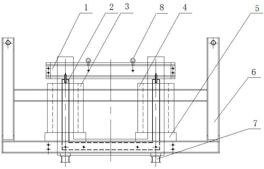
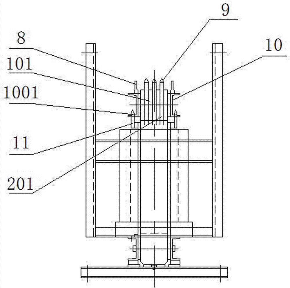
[0023] Such as Figure 1-5 As shown, a transformer for screening tests with detachable and pluggable iron cores includes an iron core, an excitation coil 3, a response coil 4, an insulating support plate 5, a bracket 7, a lifting frame 6, an excitation coil 3 and a response coil 4 set On the outside of the iron core, the iron core is a two-column iron core formed by stacking laminations. The iron core is composed of an upper iron core 1 and a lower iron core 2. The lower iron core 2 is U-shaped with two iron core columns. The iron core 1 is straight, and the upper iron core 1 is pluggably connected to the top of the lower iron core 2 .
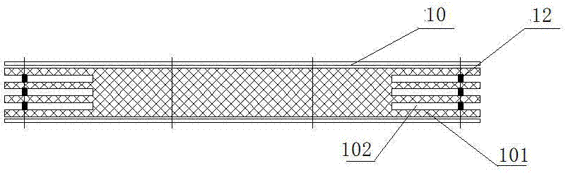
[0024] In order to connect stably and quickly, the two ends of the inline-shaped upper iron core 1 and the two ends of the U-shaped lower iron core 2 are plug-in connected. The plug-in connection i...
PUM
 Abstract
Description
Claims
Application Information