Preventive maintenance method for fatigue crack of steel box girder and steel box girder
A technology of preventive maintenance and fatigue cracks, applied in bridges, bridge maintenance, bridge reinforcement, etc., can solve the problems of poor repair methods for cracks in steel box girders, achieve good maintenance effects, save materials, and improve fatigue resistance Effect
- Summary
- Abstract
- Description
- Claims
- Application Information
AI Technical Summary
Problems solved by technology
Method used
Image
Examples
Embodiment 1
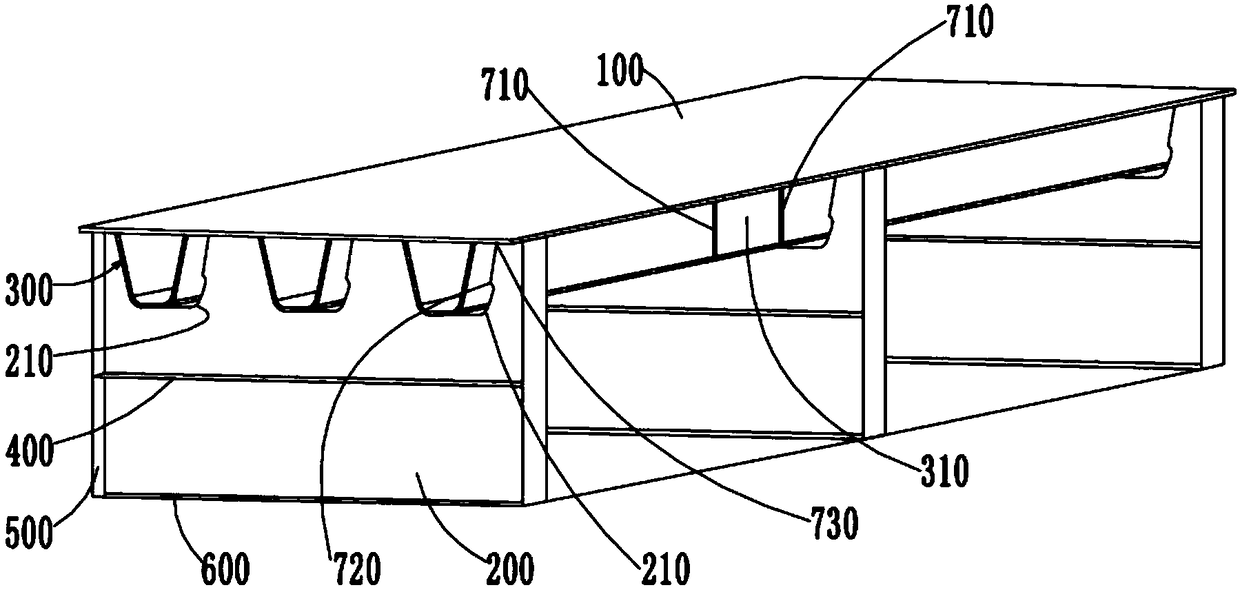
[0047] When performing preventive maintenance on the weld between the embedding section 110 and the U-shaped rib 300, the following steps are included:
[0048] S10: grinding the surface of the first welding seam 710 to be even;
[0049]S20: Grinding along the cracking direction of the coating on the first welding seam 710, so as to eliminate the microcracks on the first welding seam 710.
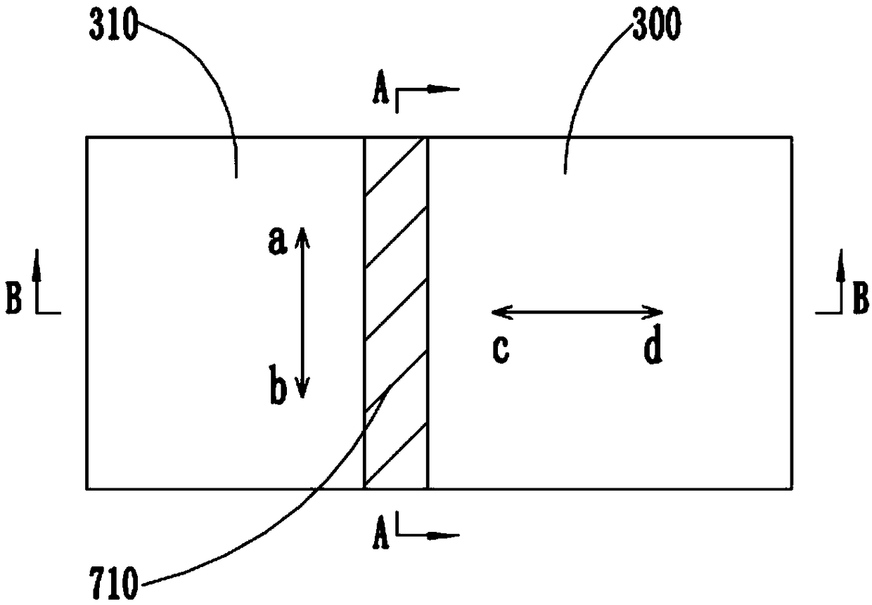
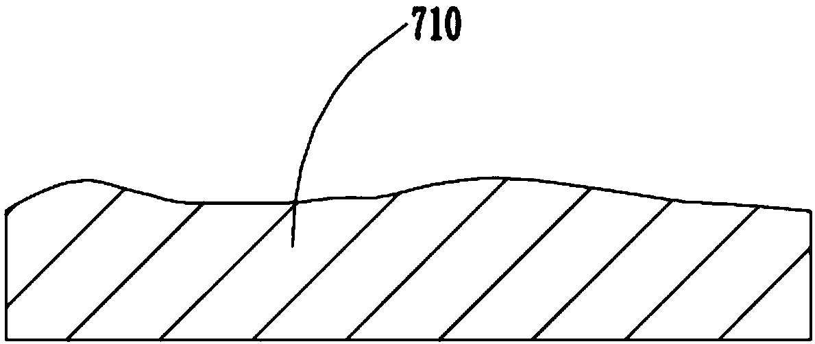
[0050] Specifically, such as Figure 2 to Figure 4 As shown, when curing the first weld 710 between the interlocking section 110 and the U-shaped rib 300, first reciprocate grinding along the direction indicated by the ab arrow, so that image 3 The uneven parts on the first welding seam 710 shown in Figure 4 The state of the first weld 710 in the middle. At this time, the surface of the first welding seam 710 is smooth and smooth.
[0051] After S10 and S20, the obvious defects on the surface of the first weld 710 are removed, so that the stress at the position of the first weld 710 i...
Embodiment 2
[0065] When maintaining the position of the arc-shaped gap 210 at the intersection of the diaphragm 200 and the lower flange of the U-shaped rib 300, it includes performing preventive maintenance on the end of the connecting weld between the U-shaped rib 300 and the diaphragm 200, and Carry out preventive maintenance on the parts of the arc gap.
[0066] Wherein, when performing preventive maintenance on the end of the connecting weld between the U-shaped rib 300 and the diaphragm 200, that is, the second weld 720, the following steps are included:
[0067] S10': grinding the surface of the second weld 720 to be flush;
[0068] S20': Grinding along the cracking direction of the coating on the second welding seam 720, so as to eliminate the microcracks on the second welding seam 720.
[0069] This step S10' and step S20' are similar to the basic operation process and function of the above step S10 and step S20, so the text will not be repeated.
[0070] When maintaining the s...
Embodiment 3
[0084] When performing preventive maintenance on the longitudinal fillet weld between the top plate 100 and the U-shaped rib 300, that is, the third weld 730, the following steps are included:
[0085] S10": grinding the surface of the third weld 730 to be flush;
[0086] S20": Grinding along the cracking direction of the coating on the third welding seam 730, so as to eliminate the microcracks on the third welding seam 730.
[0087] The basic operation process and function of the step S10 ″ and step S20 ″ are similar to those of the above step S10 and step S20 , so the description will not be repeated here.
[0088] When performing preventive maintenance on the third weld 730 between the top plate 100 and the U-shaped rib 300, the following steps are also included:
[0089] S30": grinding the third weld seam 730 again, and the grinding direction is at an angle to the cracking direction of the coating.
[0090] Preferably, the grinding direction in step S30" is perpendicular...
PUM
 Abstract
Description
Claims
Application Information
 - R&D
- Intellectual Property
- Life Sciences
- Materials
- Tech Scout
- Unparalleled Data Quality
- Higher Quality Content
- 60% Fewer Hallucinations
Browse by: Latest US Patents, China's latest patents, Technical Efficacy Thesaurus, Application Domain, Technology Topic, Popular Technical Reports.
© 2025 PatSnap. All rights reserved.Legal|Privacy policy|Modern Slavery Act Transparency Statement|Sitemap|About US| Contact US: help@patsnap.com


