
Automobile kinetic energy recycle permanent magnet synchronous generator

A kinetic energy recovery and permanent magnet synchronization technology, which is applied to synchronous motors with stationary armatures and rotating magnets, electrical components, electromechanical devices, etc., can solve the problems of restricting the development of electric vehicles, damage to the earth and humans, and long charging time , to achieve the effects of reducing charging times and time, extending mileage and reducing weight

Inactive Publication Date: 2017-07-14
谢志明
View PDF0 Cites 0 Cited by
  • Summary
  • Abstract
  • Description
  • Claims
  • Application Information

AI Technical Summary

Problems solved by technology

[0004] With the advancement of science and technology, the improvement of people's material and cultural living standards, various types of energy consumption have increased one after another, and energy problems have become increasingly prominent. Especially in the past ten years, the production of automobiles in various countries in the world has become higher and higher, and air pollution has become more and more serious. , The damage caused to the earth and human beings is immeasurable, and now all the electric vehicles in the world consume a lot of electricity, the charging time is long, and the journey is short, which restricts the development of electric vehicles. Therefore, how to solve the charging problem of electric vehicles has Is the world's top priority for the development of electric vehicles

Method used


Image

  • Automobile kinetic energy recycle permanent magnet synchronous generator
  • Automobile kinetic energy recycle permanent magnet synchronous generator

Examples


Embodiment Construction

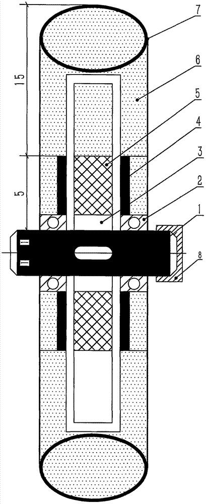
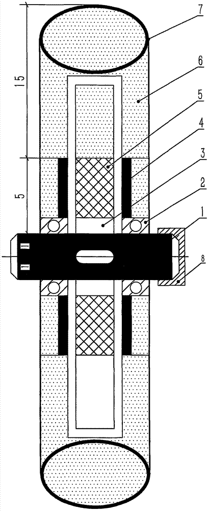
[0017] The embodiment is shown in the figure: the kinetic energy recovery permanent magnet synchronous generator for the vehicle of the present invention is composed of a disc generator, a fixed shaft (1) of the generator, an outer rotor bearing (2), an inner stator support (3), and an outer rotor It is composed of permanent magnetic poles (4), inner stator (5), outer rotor (6), outer tire (7), inner stator flange (8), and the like.

[0018] The inner stator (5) of the passive wheel generator is firmly connected to the fixed shaft (1) through the inner stator bracket (3), the outer rotor (6) is installed on the periphery of the inner stator (5), and the inner side of the outer rotor (6) is bonded in the middle Permanent magnetic poles (4), flanges (8) outside the inner stator (5) are directly used on the external fixing points, and the outer edge of the outer rotor (6) is directly connected with the rim and outer tire (7) of the passive wheel, according to the kinetic energy The ...


PUM


Abstract

The invention relates to a permanent magnet synchronous generator for vehicle kinetic energy recovery, which is a principle of converting kinetic energy into electric energy through the forward running of the vehicle, so that the generator installed on the driven wheel can generate electric energy with a set power for the driving wheel Facilities for using motors and supplementing electric energy to the driving source of electric vehicles. The facilities are mainly fixed by electric vehicle driven wheels, driven wheel generators, generator outer rotors, outer rotor permanent magnetic poles, inner stators, inner stator flanges, and outer rotors. It is composed of screw, automobile rim and outer tire. It is characterized in that: the driven wheel generator is fixed on the rim of the driven wheel through corresponding screws, and the outer rotor and the rim are connected in parallel and then closely attached to the road surface with the tire, the driving wheel is started, the outer rotor of the driven wheel generator rotates synchronously, and the recovery Its kinetic energy causes the stator winding in the generator to emit electric energy with a set power, which is used by the driving wheel motor and charged by the driving source of the electric vehicle, so that it is in a saturated state during operation.

Description

[0001] Technical field: [0002] The invention relates to a kinetic energy recovery permanent magnet synchronous generator for vehicles. It is a principle that converts kinetic energy into electrical energy through the forward movement of the vehicle, so that a generator installed on a passive wheel generates electrical energy with a set power, continuously Facilities used for driving wheel motors and for supplementing electric power for driving sources. [0003] Background technique: [0004] With the advancement of science and technology and the improvement of people's material and cultural living standards, various types of energy consumption have increased successively, and energy problems have become increasingly prominent. Especially in the past ten years, the production of automobiles in various countries in the world has been increasing, and air pollution has become more and more serious. , The damage to the earth and mankind is immeasurable, and now all electric vehicles in ...

Claims


Application Information

Patent Timeline
Patent Type & Authority Applications(China)
IPC IPC(8): H02K7/18H02K21/12
CPCH02K7/1846H02K21/12
Inventor 谢志明
Owner 谢志明
Learn More