
A pendulum-type simply supported beam piezoelectric energy harvesting device

A beam piezoelectric and energy harvesting technology, applied in the direction of piezoelectric effect/electrostrictive or magnetostrictive motors, electrical components, generators/motors, etc., can solve the problem of small deformation of piezoelectric materials and low power generation efficiency and other issues, to achieve the effect of improving power generation efficiency, strong practicability, and wide application range

Active Publication Date: 2018-10-02
HEFEI UNIV OF TECH
View PDF4 Cites 0 Cited by
  • Summary
  • Abstract
  • Description
  • Claims
  • Application Information

AI Technical Summary

Problems solved by technology

[0004] In order to improve the low-frequency characteristics of the piezoelectric energy harvesting device and make up for the defects of the ordinary cantilever beam piezoelectric energy harvesting device, such as small deformation of the piezoelectric material and low power generation efficiency under low-frequency excitation, the invention provides a pendulum-type simply supported beam Piezoelectric Energy Harvesting Devices

Method used


Image

  • A pendulum-type simply supported beam piezoelectric energy harvesting device
  • A pendulum-type simply supported beam piezoelectric energy harvesting device
  • A pendulum-type simply supported beam piezoelectric energy harvesting device

Examples


Embodiment 1

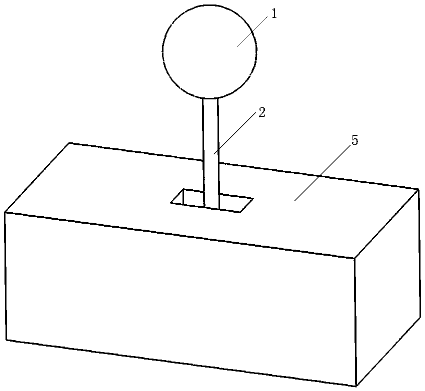
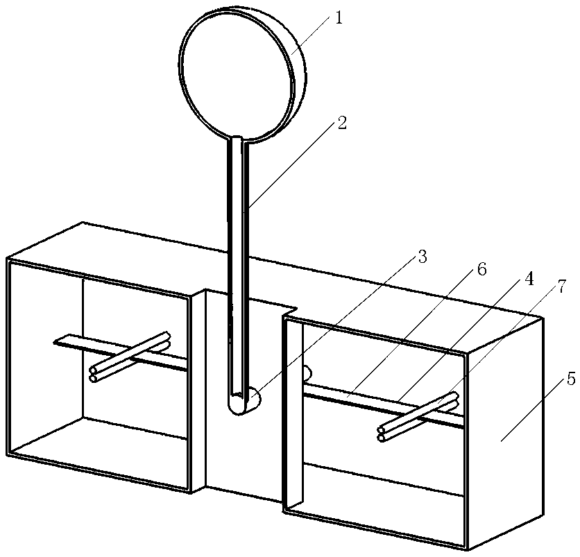
[0032] see figure 1 and figure 2 , a pendulum-type simply supported beam piezoelectric energy harvesting device includes a swing mechanism and a box body 5, the box body 5 is 300mm in height, and the material is stainless steel. The swing mechanism includes a swing ball 1, a swing rod 2, a rotating shaft 3 and four elastic simply supported beams 4. The upper and lower surfaces of the four elastic simply supported beams 4 are provided with piezoelectric elements 6, and the material of the piezoelectric elements 6 is polyvinylidene fluoride vinyl. see figure 2 , The pendulum ball 1 is a hollow ball with a diameter of 200mm.

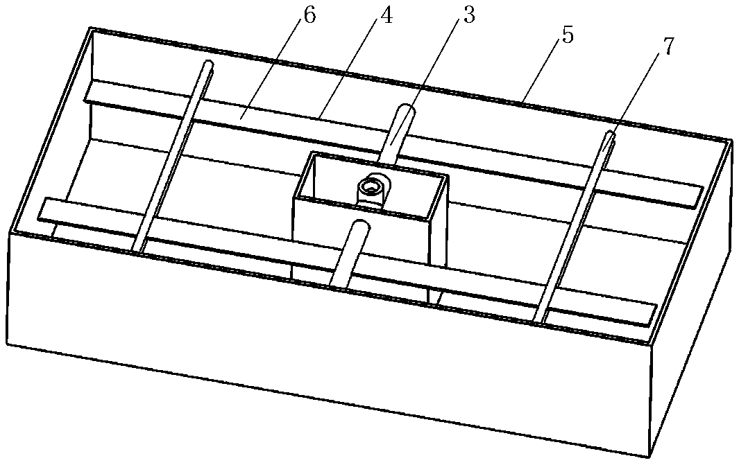
[0033] see Figure 4 and image 3 , the length of the swing rod 2 is 400 mm, one end of the swing rod 2 is fixedly connected to the swing ball 1, and the other end is fixedly connected to the middle part of the rotating shaft 3, and the maximum deflection angle of the swing rod 2 is ±28°. Both sides of the rotating shaft 3 are respectively fixedly c...

Embodiment 2

[0044] see Figure 8 , In the present embodiment, the pendulum ball 1 is a solid ball with a diameter of 100mm, and the working environment of the device is in the air. Other structures are the same as embodiment 1, and the working principle is the same as embodiment 1.

[0045] The invention has strong practicability, wide application range and can work in various environments. It can be installed in rivers, lakes or offshore places to collect kinetic energy of water bodies, and can also be used for vibration energy collection of mechanical structures, building structures, etc. It can collect and supply energy for low-power microelectronic components without consuming any fossil energy. An environmentally friendly energy harvesting device.


PUM


Abstract

The invention discloses a swing ball type simple supported beam piezoelectric energy collecting device. The device comprises a swing mechanism and a box body; the swing mechanism comprises a swing ball, a swing rod, a rotating shaft and four elastic simple supported beams, and a surface of each of the four elastic simple supported beams is provided with a piezoelectric element; the swing ball is connected with one end of the swing rod, and the other end of the swing rod is fixedly connected with the middle part of the rotating shaft; two sides of the rotating shaft are respectively and fixedly connected with ends of the two elastic simple supported beams; the swing ball locates outside the box body, and the rotating shaft and the elastic simple supported beams locate in the box body; and two sides of the rotating shaft are separately provided with a pair of clamping rods, the two pairs of the clamping rods separately clamp the other ends of the elastic simple supported beams and play a role in constraint limit for the other ends of the elastic simple supported beams in a vertical direction. The device works in air or water area environment. When the swing ball feels an external vibration excitation and swings, the four elastic simple supported beams are driven to generate elastic bending deformations, and the piezoelectric elements generate deformations with the elastic bending deformations of the elastic simple supported beams and generate charges. The device has the advantages of simple structure and high practicability, and can effectively collect vibration energy in environment.

Description

technical field [0001] The invention belongs to the field of energy recovery, adopts vibration piezoelectric energy conversion technology, and mainly relates to a pendulum-type simply supported beam piezoelectric energy collection device. Background technique [0002] With the continuous development of wireless communication and MEMS technology, the application range of microelectronic chips and micro sensors has been continuously expanded. Most of these devices still rely on traditional chemical batteries for power supply, such as nickel metal hydride batteries and lithium polymer batteries. Traditional chemical batteries have a limited lifespan and need to be replaced or recharged after a period of use, which is a serious constraint for wireless sensors placed in harsh climates or remote areas. At the same time, a large number of batteries will also cause harm to the environment. Therefore, energy harvesting technology has become the focus of research at home and abroad. ...

Claims


Application Information

Patent Timeline
Patent Type & Authority Patents(China)
IPC IPC(8): H02N2/18
CPCH02N2/186
Inventor 邓华夏杜宇王哲敏于连栋张进马孟超钟翔
Owner HEFEI UNIV OF TECH
Learn More