Circular conveying apparatus

A conveying device and circulating technology, applied in the direction of conveyors, conveyor objects, vibrating conveyors, etc., can solve the problems of blocked conveying, conveying action obstacles, conveying pollution, etc., so as to reduce poor conveying or conveying pollution, realize high speed effect

Active Publication Date: 2017-07-18
DAISHIN CO LTD
View PDF4 Cites 5 Cited by
  • Summary
  • Abstract
  • Description
  • Claims
  • Application Information

AI Technical Summary

Problems solved by technology

If the miniaturization of the conveyed objects develops in this way, the following problems are likely to occur: the conveyed objects are clogged in the conveying path or adhered to the conveying surface due to dust, etc. Transport pollution and other issues
In addition, in the above-mentioned recovery transfer unit and supply transfer unit where the two transfer bodies face each other with a slight gap and height difference, there are also situations where the transfer operation is hindered by the stuck objects or dust clogging.
[0009] In addition, since the assembly line speed in the production line of the electronic system is also increasing at the same time as the miniaturization of the above-mentioned electronic devices, an increase in the speed of the conveyance and a high density of the conveyance form are also required for the conveyance device. When an electronic device in an improper posture is accidentally supplied, the assembly line stop time for recovery will increase the loss, so the requirement for the alignment accuracy of the transported objects is also increasing.

Method used


Image

  • Circular conveying apparatus
  • Circular conveying apparatus
  • Circular conveying apparatus

Examples


Embodiment Construction

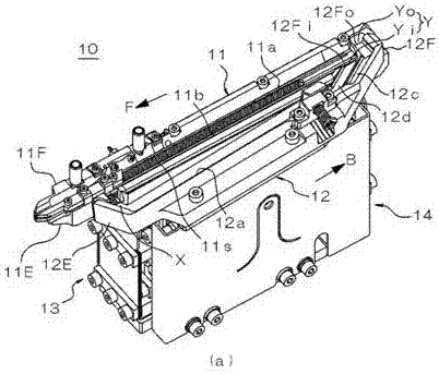
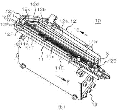
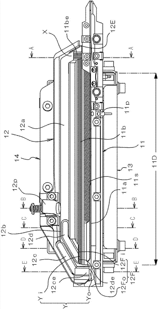
[0068] Next, an embodiment of the circulating conveying device according to the present invention will be described in detail with reference to the drawings. Figure 1 to image 3 It is an external view showing the whole device of this embodiment, Figure 4 to Figure 8 yes figure 2 Enlarged cross-sectional view of each part shown.

[0069] The circulating conveying device 10 of the present embodiment includes a supply-side conveying body 11 mounted on an upper portion of a supply-side vibrating mechanism 13 , and a collection-side conveying body 12 mounted on an upper portion of a collecting-side vibrating mechanism 14 . The supply-side conveyance body 11 and the recovery-side conveyance body 12 are attached in a posture parallel to each other. The supply-side conveyor 11 is composed of a base block 11E mounted on the upper portion of the supply-side vibration excitation mechanism 13 and an attachment block 11F attached to the upper portion of the base block 11E.

[0070] T...


PUM


Abstract

An objective of the invention is to realize a circular conveying apparatus which can reduce bad conveying or conveying pollution generated with micromation of conveyed objects, and is helpful to realize high speed of conveying height or high density of conveying forms. The circular conveying apparatus (10) is provided with a recycling transfer portion (X) which makes conveyed objects excluded by a supply side arrangement path (11a) transfer to a recycling side conveying path (12a), and a supply transfer portion (Y) which makes conveyed objects conveyed by the recycling side conveying path (12a) transfer to the supply side arrangement path (11a). In the recycling transfer portion (X), a downstream end of an excluding path of the conveyed objects from the supply side arrangement path (11a) is above an upstream portion of the recycling side conveying path (12a) and hangs over, or in the supply transfer portion (Y), a downstream end of the recycling side conveying path (12a) is above an upstream portion of the supply side arrangement path (11a) and hangs over.

Description

technical field [0001] The present invention relates to a circulating conveying device, and more particularly, to a structure of a conveying body of a circulating conveying device that returns conveyed objects removed from an arraying path to an upstream side while aligning conveyed objects on an arraying path, and resupplies them to the arraying path. Background technique [0002] In general, there is a type of conveying device configured to convey conveyed objects in an arrayed state uniformly in a desired posture by controlling the posture of conveyed objects during conveyance. As such a conveying device, for example, a vibrating conveying device called a parts feeder or a linear feeder is known. In such a conveying device, the conveyed objects that are not in the desired posture are shaken off or blown away by airflow while conveying the conveyed objects on the alignment path, thereby sorting the conveyed objects or turning the conveyed objects, etc. By changing the pos...

Claims


Application Information

Patent Timeline
Patent Type & Authority Applications(China)
IPC IPC(8): B65G27/04B65G27/24B65G27/34
CPCB65G27/04B65G27/24B65G27/34B65G47/14B65G2812/0388
Inventor 古田光山田泰原顺一神户祐二赤岩诚山本笃史百濑和纪皆川恭弘
Owner DAISHIN CO LTD
Why Eureka
Try Eureka