Measurement device and method for transmission wavefronts of self-focusing lens

A technology of self-focusing lens and measuring device, which is applied in the field of optics, can solve the problems of affecting measurement results, large numerical aperture, and small size, and achieve the effects of improving measurement accuracy, high confidence, and good repeatability

Pending Publication Date: 2017-07-18
崔京杰
View PDF8 Cites 12 Cited by
  • Summary
  • Abstract
  • Description
  • Claims
  • Application Information

AI Technical Summary

Problems solved by technology

Since the working band of the self-focusing lens is visible light, the numerical aperture is large, the overall size is small, and the two ends are parallel planes, the use of interferometry to measure the transmitted wavefront of the self-focusing lens has the following disadvantages: 1) The laser interferometer works at a single wavelength and cannot achieve white light. Transmission wavefront measurement; 2) The static phase-shifting laser interferometer driven by piezoelectric ceramics is easily affected by air flow disturbance and vibration, and the dynamic laser interferometer only works in a specific band, and the test efficiency and economy are poor; 3) Due to the The reflections on both ends of the focusing lens make the interference fringes superimposed on each other, which seriously affects the measurement results of the transmitted wavefront
Therefore, the use of laser interferometers cannot meet the needs of self-focusing lens transmission wavefront testing

Method used


Image

  • Measurement device and method for transmission wavefronts of self-focusing lens

Examples


Embodiment Construction

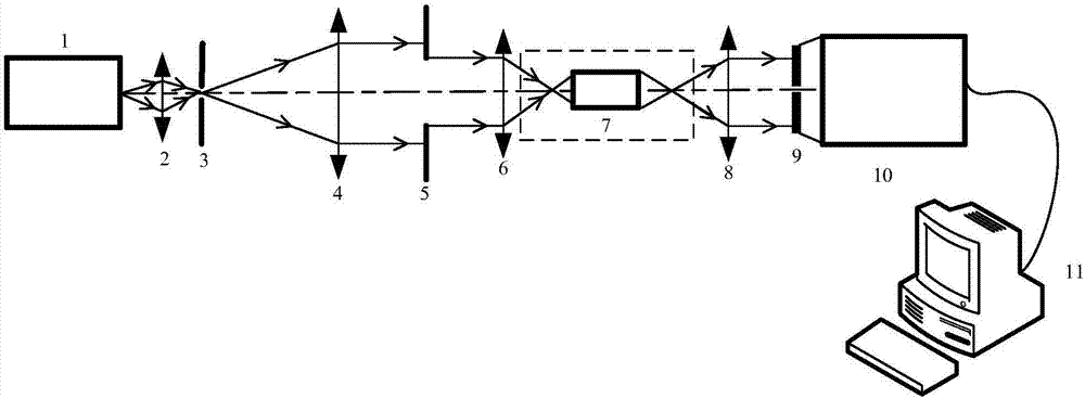
[0035] see figure 1 , the present invention provides a self-focusing lens transmission wavefront measurement device, the self-focusing lens transmission wavefront measurement device includes a light source 1, a converging mirror 2, a target plate 3, a collimating mirror 4, a diaphragm 5, a first microscope Objective lens 6, second microscope objective lens 8, positioning reference structure 9, Shack-Hartmann wavefront sensor 10 and computer 11; converging lens 2, target plate 3, collimating lens 4, aperture 5, first microscope The objective lens 6, the second microscopic objective lens 8, the positioning reference structure 9 and the Shaker-Hartmann wavefront sensor 10 are sequentially arranged on the outgoing light path of the light source 1; the Shaker-Hartmann wavefront sensor 10 is connected to the computer 11; The self-focusing lens 7 to be tested is placed between the first microscopic objective lens 6 and the second microscopic objective lens 8 . figure 1 In , the blac...


PUM


Abstract

The invention belongs to the field of optics, and relates to a measurement device and method for transmission wavefronts of a self-focusing lens. The measurement device for the transmission wavefronts of the self-focusing lens comprises a light source, a convergent mirror, a target plate, a collimating mirror, an aperture, a first microscope objective, a second microscope objective, a positioning reference structure, a Shack-Hartmann wavefront sensor and a control computer; the convergent mirror, the target plate, the collimating mirror, the aperture, the first microscope objective, the second microscope objective, the positioning reference structure and the Shack-Hartmann wavefront sensor are successively arranged on an emergent light path of the light source; the Shack-Hartmann wavefront sensor is connected with the control computer; the self-focusing lens to be detected is placed between the first microscope objective and the second microscope objective. The invention provides the measurement device and method for the transmission wavefronts of the self-focusing lens based on the Shack-Hartmann wavefront sensor, which is free from external environmental influences and capable of guaranteeing test precision.

Description

technical field [0001] The invention belongs to the field of optics, and relates to a self-focusing lens transmission wavefront measurement device and method, in particular to a self-focusing lens transmission wavefront measurement device and method based on a Shack-Hartmann wavefront sensor. Background technique [0002] Self-focusing lens, also known as gradient variable refractive index lens, refers to a cylindrical optical lens whose refractive index distribution is gradually changed along the radial direction. It can cause continuous refraction of the light transmitted along the axial direction, so as to realize the smooth and continuous convergence of the outgoing light to one point. Due to the end face collimation, coupling and imaging characteristics of the gradient index lens, coupled with its small cylindrical shape, it is not only successfully used in the imaging field (copiers, fax machines, endoscopes and optical disc lenses, etc.), but also in optical fibers I...

Claims


Application Information

Patent Timeline
Patent Type & Authority Applications(China)
IPC IPC(8): G01M11/02
CPCG01M11/02
Inventor 崔京杰
Owner 崔京杰
Why Eureka
Try Eureka